Novel stock fluid deironing method and device

A slurry and fluid technology, applied in the field of mineral beneficiation methods and devices, can solve the problems of many action steps, affecting the cleaning speed of the magnetic bar, and the magnetic bar cannot be put into use quickly, and achieves a technology with fewer action mechanisms and fewer cleaning steps. Effect

Inactive Publication Date: 2012-05-23
李泽
View PDF0 Cites 0 Cited by
  • Summary
  • Abstract
  • Description
  • Claims
  • Application Information

AI Technical Summary

Problems solved by technology

[0002] The magnetic rod cleaning in the existing magnetic rod type slurry fluid iron removal technology generally includes sending the magnetic rod forward to the cleaning room, putting a scraper on the magnetic rod, and moving the magnetic rod backward to make the scraper remove the iron on the magnetic rod. The magnetic material is scraped off and the magnetic rod is rinsed with a flushing device at the same time. The whole process requires three steps and two action mechanisms. The two action mechanisms are the movement of the magnetic rod and the opening and closing of the scraper sleeve. Parts are in contact with the slurry, and the slurry is easy to penetrate into the transmission part. Once the slurry penetrates into the transmission part, it will seriously affect the normal operation of the transmission part. In addition, there are many action steps, which also affect the magnetic The cleaning speed of the rod, so that the magnetic rod cannot be put into use soon

Method used


Image

  • Novel stock fluid deironing method and device
  • Novel stock fluid deironing method and device
  • Novel stock fluid deironing method and device

Examples


Embodiment Construction

[0014] Now in conjunction with accompanying drawing and embodiment the present invention is described in further detail:

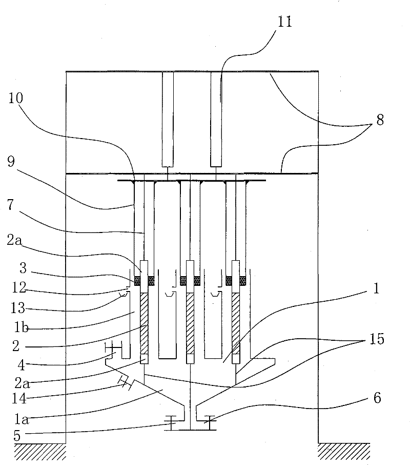
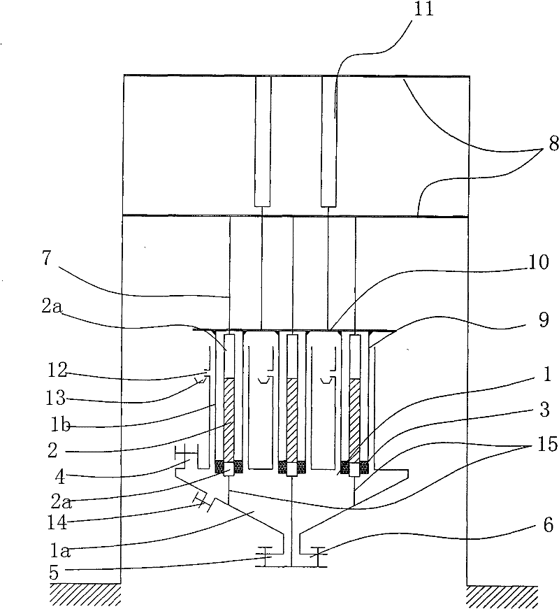
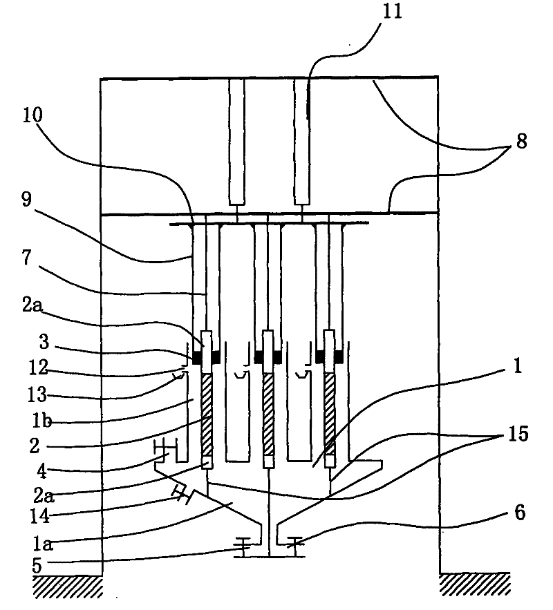
[0015] As shown in the figure, the new slurry fluid iron removal method of the present invention is realized in this way, including the slurry fluid iron removal process and the magnetic bar cleaning process. The slurry fluid iron removal process is that the slurry fluid flows from the bottom of the vertical cavity to After the permanent magnet rod installed vertically in the chamber to remove iron, it flows out from the outlet on the upper side of the chamber to the slurry tank; the cleaning process of the magnetic rod is to stop the iron removal process of the slurry fluid first, and remove the iron in the chamber. The slurry fluid is drained away, and then the scraper set on the top of the permanent magnet rod is moved down along the permanent magnet rod through the power mechanism, and the ferromagnetic substance attached to the permanent magnet rod is ...


PUM


Abstract

The invention relates to a novel stock fluid deironing method and a device, which is characterized by comprising a stock fluid deironing process and a magnetic rod washing process, wherein the tock fluid deironing process is that: the stock fluid flows upwards from the bottom part of a vertical cavity, and the stock fluid flows out to a stock groove from an outlet on the side surface of the upperpart of the cavity after being deironized by a permanent-magnetic body rod which is vertically arranged inside the cavity; and the magnetic rod washing process is that: the stock fluid deironing process is firstly stopped, then a scraping sleeve which is previously arranged on the top part of the permanent-magnetic rod is moved downwards along the permanent-magnetic body rod through a power mechanism, so the ferromagnetic substance which is attached onto the permanent-magnetic body rod is scraped onto a non-magnetic conductive material rod on the lower end of the permanent-magnetic body rod, the ferromagnetic substance is washed away from the non-magnetic conductive material rod on the lower end of the permanent-magnetic body rod through a washing device, the washed-away ferromagnetic substance is discharged through a drain valve which is arranged below the cavity, and the scraping sleeve is pulled back to the top part of the permanent-magnetic rod through the power mechanism so as toreprocess the stock fluid deironing process. Compared with the prior art, the novel stock fluid deironing method has the advantages that the cleaning steps are fewer, the actuating mechanisms are fewer and the actuating mechanism is free from being influenced by the penetration of the stock.

Description

Technical field: [0001] The invention relates to a mineral separation method and device. Background technique: [0002] The magnetic rod cleaning in the existing magnetic rod type slurry fluid iron removal technology generally includes sending the magnetic rod forward to the cleaning room, putting a scraper on the magnetic rod, and moving the magnetic rod backward to make the scraper remove the iron on the magnetic rod. The magnetic material is scraped off and the magnetic rod is rinsed with a flushing device at the same time. The whole process requires three steps and two action mechanisms. The two action mechanisms are the movement of the magnetic rod and the opening and closing of the scraper sleeve. Parts are in contact with the slurry, and the slurry is easy to penetrate into the transmission part. Once the slurry penetrates into the transmission part, it will seriously affect the normal operation of the transmission part. In addition, there are many action steps, which...

Claims


Application Information

Patent Timeline
Patent Type & Authority Patents(China)
IPC IPC(8): B03C1/02
Inventor 李泽
Owner 李泽
Why Eureka
Try Eureka