Supercharge Your Innovation With Domain-Expert AI Agents!

Device for reducing water projection for a tyre

一种轮胎、胎面的技术,应用在轮胎零部件、轮胎胎面/胎面花纹、外胎侧壁等方向,能够解决温度升高等问题,达到降低排出流体的动力的效果

Inactive Publication Date: 2012-06-20
SOCIETE DE TECH MICHELIN
View PDF1 Cites 0 Cited by
  • Summary
  • Abstract
  • Description
  • Claims
  • Application Information

AI Technical Summary

Problems solved by technology

[0009] In addition, the technical solution described in this patent makes it possible to limit the increase in temperature within the tread, especially near the end of the crown reinforcement ply

Method used


Image

  • Device for reducing water projection for a tyre
  • Device for reducing water projection for a tyre
  • Device for reducing water projection for a tyre

Examples


Embodiment Construction

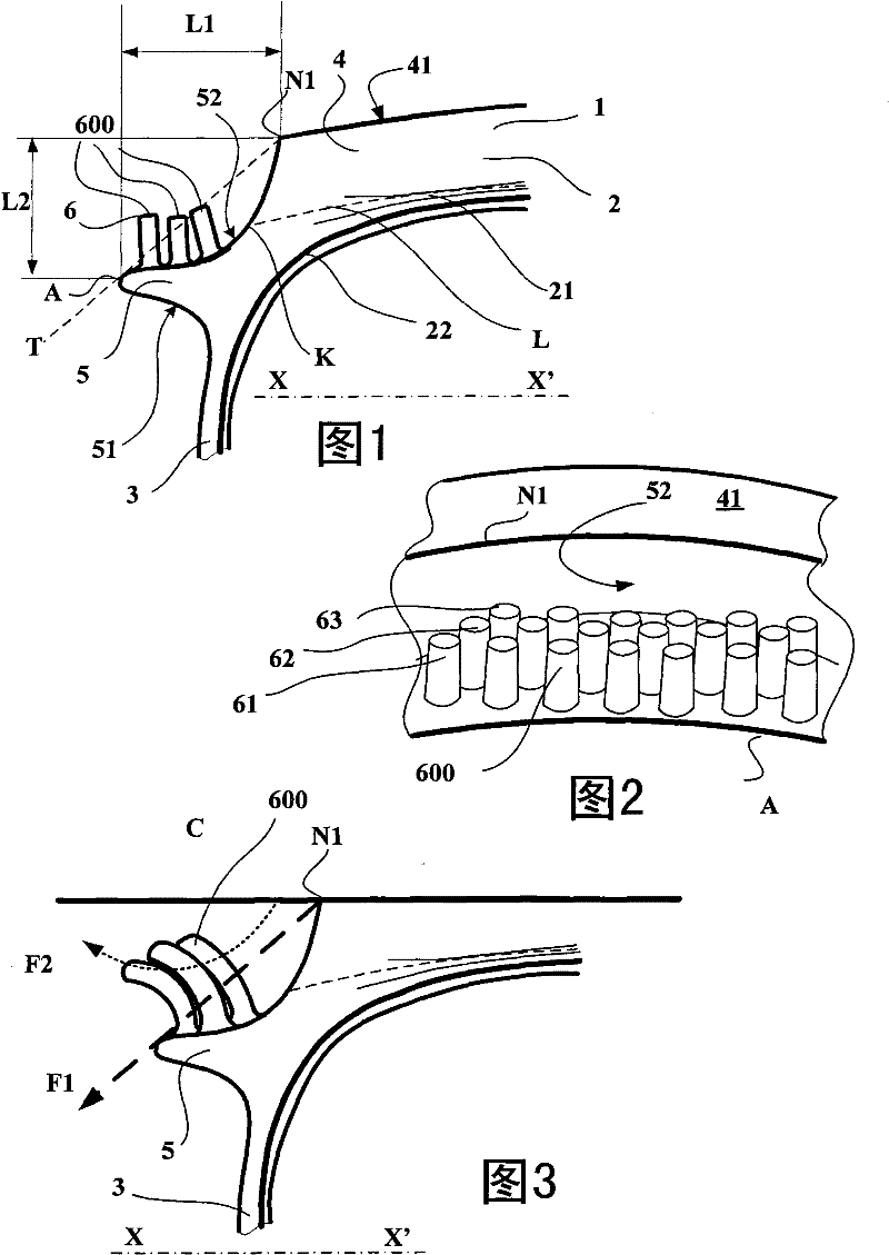
[0037] figure 1 A meridian section is shown, ie containing the tire's axis of rotation (the axis parallel to figure 1A partial sectional view of a heavy goods vehicle tire 1 according to the invention in a plane in the direction indicated by the line XX' in . This tire 1 of size 385 / 55R 22.5 comprises a crown region 2 connected by sidewalls 3 to beads (not shown). The crown 2 of the tire comprises a tread 4 having a radially outer running surface 41 intended to come into contact with the road when the tire is running. This surface 41 terminates axially in a line whose intersection with the profile corresponds to point N1 . It can be seen in the section of this figure that the point N1 corresponds to the axially outermost point of the contact trace of the running surface 41 of the tire under rated running conditions.

[0038] On the sidewall 3 there are shown ribs 5 protruding towards the outside of the tire (the inside of the tire corresponding by definition to the tire cav...


PUM


Abstract

The invention relates to a tyre (1) having a tread (4), flanges (3) extending from the edges of the tread and, on at least one of said flanges, a rib (5) for modifying the trajectory of water projections in case of rolling on a wet ground, said rib (5) further including a force reducing device (6) provided on the outer wall of the rib in order to reduce the force of the water projections in a transverse direction during rolling on a water-covered ground, said force reducing device (6) including at least one protrusion (600) arranged in the circumferential direction and extending in the radialdirection.

Description

technical field [0001] The present invention relates to tires for heavy-duty road vehicles, and in particular to tires provided with means for deflecting or diverting water discharged laterally when a vehicle equipped with said tires travels on a road covered with water. Background technique [0002] When driving in the rain, the maneuver of overtaking or catching up with a heavy goods vehicle is often dangerous for other road users, as large quantities of water may be drained sideways from the vehicle, splashing other vehicles The windshield of these vehicles will significantly reduce the visibility of the drivers of these vehicles. [0003] Tires for heavy goods vehicles generally consist of two beads intended to come into contact with the rim, a crown provided with a tire having a running surface and two sidewalls (sidewalls) The running surface is used to contact the ground when the vehicle is running, and the two sidewalls are used to connect the tread with the bead. ...

Claims


Application Information

Patent Timeline
Patent Type & Authority Patents(China)
IPC IPC(8): B60C19/00B60C11/01
CPCB60C13/023B60C2011/013B60C13/02B60C11/01
Inventor J-M·达尔古C·维斯
Owner SOCIETE DE TECH MICHELIN
Features
  • R&D
  • Intellectual Property
  • Life Sciences
  • Materials
  • Tech Scout
  • Unparalleled Data Quality
  • Higher Quality Content
  • 60% Fewer Hallucinations
Learn More