

Flexible mount for a fan and like devices
一种柔性、风扇的技术,应用在用于弹性流体的泵送装置的部件、机械设备、泵元件等方向,能够解决大量部件和部件库存量、短路、风扇不可操作等问题,达到快速且容易安装的效果
- Summary
- Abstract
- Description
- Claims
- Application Information
AI Technical Summary
Problems solved by technology
Method used
Image

Examples
Embodiment Construction
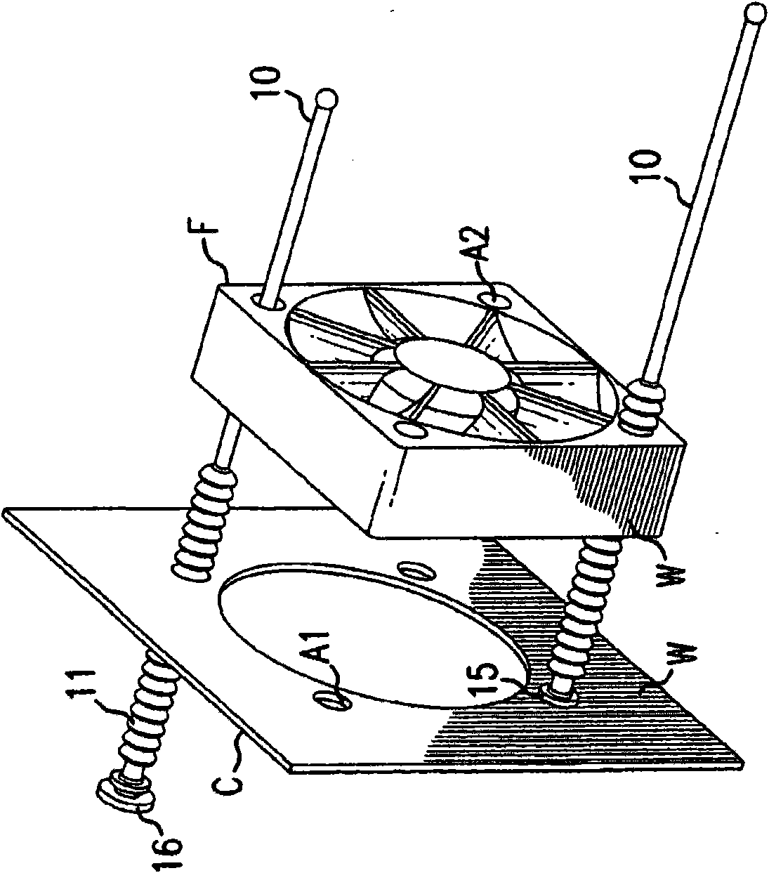
[0026] refer to Figure 1-4 , a typical frame F is attached to a chassis or panel C by a mounting device 10 embodying the invention. The frame F and the panel C have respective holes A1 and A2 for receiving the mounting device 10 . Frame F may contain fan B, which is subject to vibration and requires a resilient mounting system.
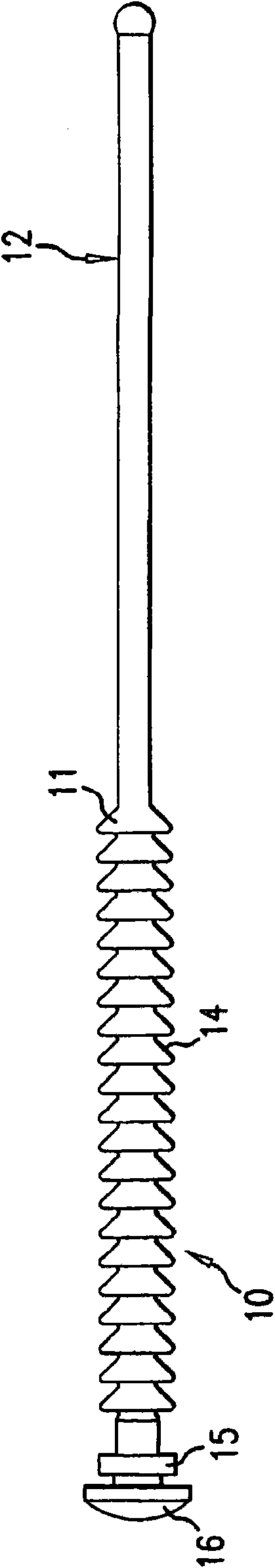
[0027] Mounting device 10 is preferably molded from silicone rubber and can be stretched longitudinally. The mounting device 10 is preferably formed with a series of enlarged axially spaced undulations 11 having a diameter larger than the holes A1 and A2 of the frame F and chassis C, and the shaft 12 of the mounting device 10 generally has these Diameter of holes A1 and A2. The front surface 14 of these undulations 11 is preferably tapered towards the axis 12, and the mounting device 10 can be elongated sufficiently to allow the undulations to pass through apertures A1 and A2 when elongated, and to snap around when undone. The wall W of the hole....
PUM
 Abstract
Description
Claims
Application Information