Adjustable Handle Toothbrush

Inactive Publication Date: 2010-03-04
HUPENCE MICHAEL J
View PDF5 Cites 1 Cited by
  • Summary
  • Abstract
  • Description
  • Claims
  • Application Information

AI Technical Summary

Benefits of technology

[0014]The present invention achieves the above objects, among others, by providing, in a preferred embodiment, a flexible toothbrush that can be angled into two or more positions and locked into place so that it stays in place while brushing. Th

Problems solved by technology

However there is not yet a non-disposable toothbrush handle that allows the simple, manual angling and angle locking that this proposed construction offers.
The proposed toothbrush offers three or fewer parts to accomplish the same goal as the previous, control-pin device, which has more parts and is more difficult to operate.
An elastically deformable neck does not allow for a locking/secure positioning mechanism, as the proposed one does.
In addition to being a novelty item, the purpose

Method used


Image

  • Adjustable Handle Toothbrush
  • Adjustable Handle Toothbrush
  • Adjustable Handle Toothbrush

Examples


Embodiment Construction

[0022]In general, the present invention has arisen to mitigate and / or obviate the disadvantages of current toothbrush devices and methods of angling a toothbrush.

[0023]These and other objects, features and advantages of the present invention will become apparent by referring to the following description of preferred embodiments. The drawings below are for illustration only. The figure numerals in parentheses refer to the figure in which the element(s) being described are more fully shown. The element(s) may also be shown on other figures.

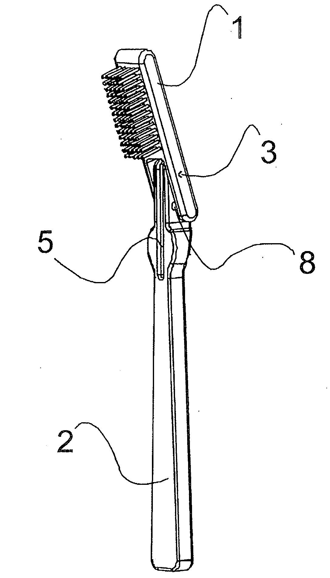
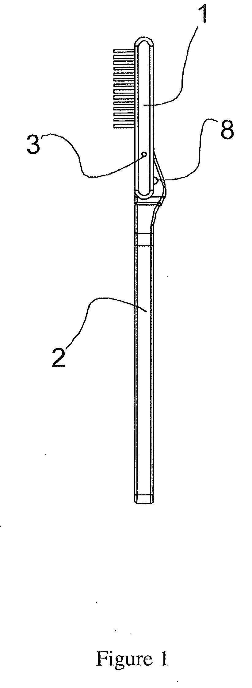
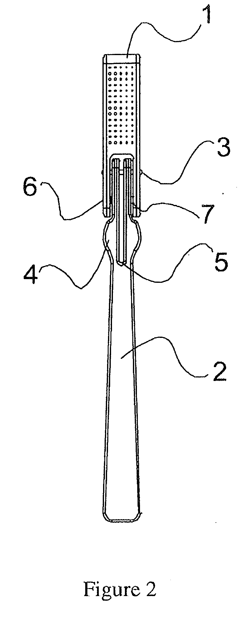
[0024]In FIGS. 1 through 7, the toothbrush head 1 connects to the handle via a stationary hinge pin 3 plus a set of detents 7 on either side of the head that lock into a set of dimples 8 on either side of the handle 2. The detents 7 are located on the inside of two opposing legs 6 of the toothbrush head. The detents 7 in the legs 6 fit into the dimples 8 in the handle.

[0025]The toothbrush head 1 has a hole 10 in it for the hinge pin 3. The handle al...


PUM


Abstract

In a preferred embodiment, this invention provides an easy-to-use, adjustable-head toothbrush that provides two or more locking angles for brushing.

Description

BACKGROUND OF THE INVENTION[0001]1. Field of the Invention[0002]This invention relates to toothbrushes and more particularly to an adjustable-head toothbrush that provides two or more locking angles of the brush head.[0003]2. Prior Art[0004]Among the thousands of toothbrush inventions are those that adjust into angles. Earlier designs include devices that fold, tilt, allow head-replacement and head-disposal, offer a novelty handle design, and other actions. However there is not yet a non-disposable toothbrush handle that allows the simple, manual angling and angle locking that this proposed construction offers. The following application and patents show adjustable toothbrush devices.[0005](a) U.S. Pat. No. 4,731,896: a toothbrush which requires finger manipulation of a control pin to adjust a handle that consists of two hinged parts and a pivot. The proposed toothbrush offers three or fewer parts to accomplish the same goal as the previous, control-pin device, which has more parts a...

Claims


Application Information

Patent Timeline
IPC IPC(8): B25G1/04A46B9/04B25G1/06
CPCA46B5/0075B25G1/06A46B2200/1066A46B5/0083
Inventor HUPENCE, MICHAEL J.
Owner HUPENCE MICHAEL J
Why Eureka
Try Eureka