
Direct current relay having permanent magnet housing

A technology of DC relays and permanent magnets, applied in the direction of electromagnetic relays, relays, detailed information of electromagnetic relays, etc., can solve the problems of large operating procedures, increased manufacturing costs, and inability to accurately control arcs, etc., and achieves wide contact area and easy manufacturing Effect

Active Publication Date: 2020-08-07
LS ELECTRIC CO LTD
View PDF15 Cites 2 Cited by
  • Summary
  • Abstract
  • Description
  • Claims
  • Application Information

AI Technical Summary

Problems solved by technology

Accordingly, a large number of work steps are required and the manufacturing cost is increased
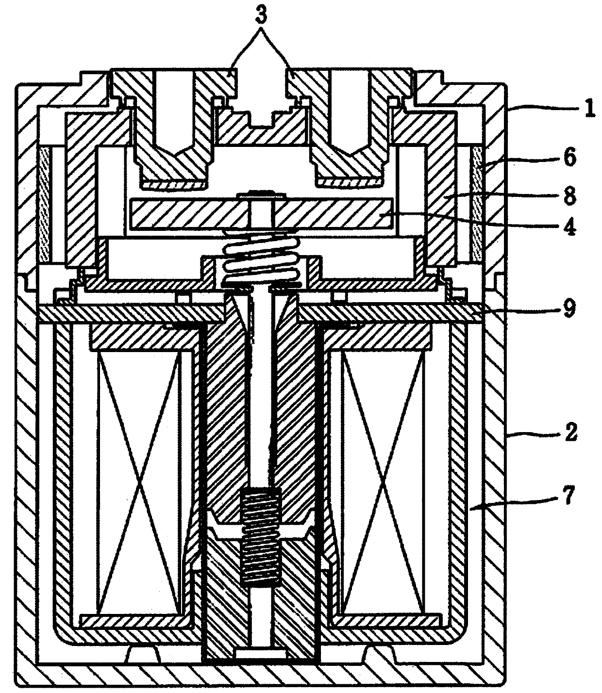
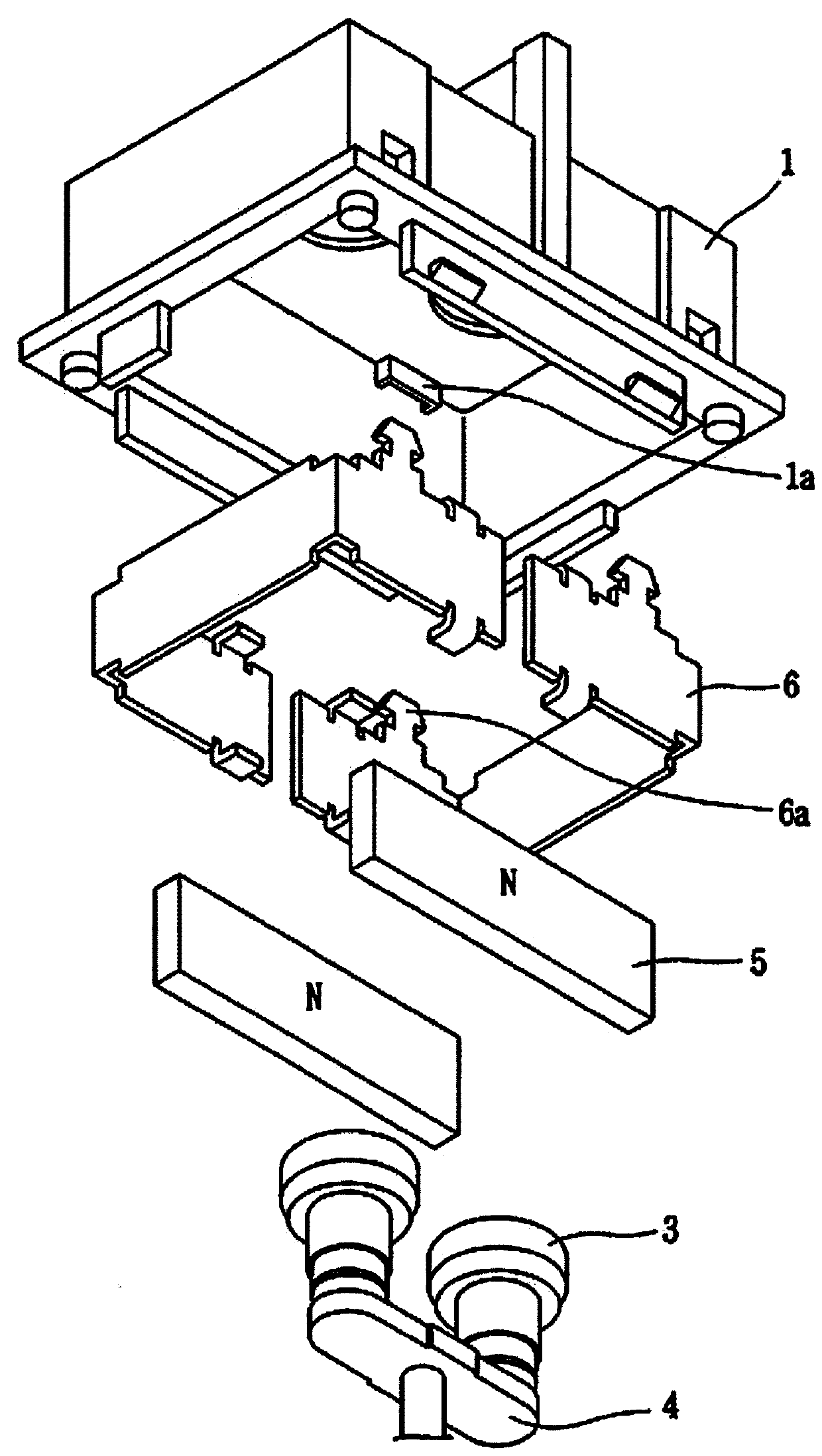
[0010] In addition, since the permanent magnet holder 6 is press-fitted into the upper frame 1 to manufacture the structure, if it cannot be accurately placed on the jig during the manufacturing process, or the permanent magnet holder 6 is removed from the placement portion 1a of the upper frame 1 If the permanent magnet 5 falls off, the arc generated when the permanent magnet 5 is broken and disconnected cannot be accurately controlled, resulting in failure or shortened product life.

Method used


Image

  • Direct current relay having permanent magnet housing
  • Direct current relay having permanent magnet housing
  • Direct current relay having permanent magnet housing

Examples


Embodiment Construction

[0042] Hereinafter, preferred embodiments of the present invention will be described with reference to the accompanying drawings. This is a detailed description to enable those of ordinary skill in the art to implement the invention easily, and this does not mean to limit the technical idea and scope of the present invention.

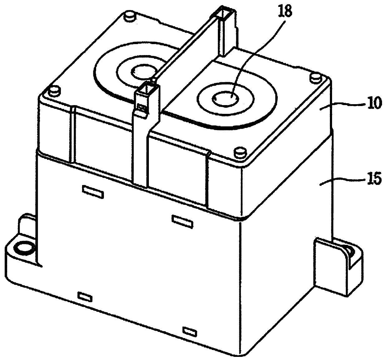
[0043] image 3 is a perspective view of a DC relay according to an embodiment of the present invention, Figure 4 yes image 3 A perspective view of the lower part of the DC relay shown, Figure 5 It is a perspective view of a permanent magnet assembly and an upper frame applied to a DC relay according to an embodiment of the present invention. Referring to the accompanying drawings, the DC relays provided with permanent magnet housings according to various embodiments of the present invention will be described in detail.

[0044] A DC relay with a permanent magnet housing according to an embodiment of the present invention includes: an upper frame ...


PUM


Abstract

The present invention relates to a direct current relay and, more specifically, to a direct current relay having a permanent magnet housing. A direct current relay having a permanent magnet housing according to one embodiment of the present invention comprises: an upper frame having an open lower surface, and a lower frame having an open upper surface and coupled to the lower portion of the upperframe; a permanent magnet housing formed in a box shape having an open lower surface, disposed inside the upper frame or lower frame, and having a permanent magnet insertion portions provided on eachof the front surface and the rear surface thereof; a permanent magnet arranged in the permanent magnet insertion portion; and a permanent magnet holder coupled to the permanent magnet housing and supporting the permanent magnet.

Description

technical field [0001] The present invention relates to a direct current relay, and more specifically, relates to a direct current relay provided with a permanent magnet housing. Background technique [0002] Generally, a DC relay (Direct Current Relay) or a magnetic contactor (Magnetic Contactor) is a circuit switching device that uses the principle of an electromagnet to transmit mechanical drive and current signals, and is installed in various industrial equipment, machinery, and vehicles. [0003] In particular, electric vehicles (Electric Vehicles) such as hybrid vehicles, fuel cell vehicles, golf carts, and electric forklifts are equipped with an Electric Vehicle Relay (Electric Vehicle Relay) for supplying electric power from a battery to The power generation device and the electric part, or cut off the electric power of the battery supplied to the power generation device and the electric part. This DC relay is one of the very important core components for electric v...

Claims


Application Information

Patent Timeline
Patent Type & Authority Applications(China)
IPC IPC(8): H01H50/04
CPCH01H50/04H01H50/041
Inventor 朴轸熙
Owner LS ELECTRIC CO LTD
Learn More