Blast furnace coal gas pressure reducing valve

A blast furnace gas and pressure reducing valve technology, used in safety valves, balance valves, valve devices, etc., can solve the problems of uneven air flow, large wear and tear of the pressure reducing valve group, and large airflow disturbance, and achieve the reduction of pipeline vibration and sealing performance. Improve and reduce the effect of comprehensive investment

Inactive Publication Date: 2010-09-15
WISDRI ENG & RES INC LTD
View PDF0 Cites 7 Cited by
  • Summary
  • Abstract
  • Description
  • Claims
  • Application Information

AI Technical Summary

Problems solved by technology

[0005] 1. Since the regulating element of the pressure reducing valve group is a valve plate, its air flow is not uniform, and when the high pressure gas is reduced to low pressure gas, the noise generated is quite large;
[0006] 2. Due to the large disturbance of the air flow, the vibration of the pipeline is large;
[0007] 3. When the semi-static gas is released, the wear of the pressure reducing

Method used


Image

  • Blast furnace coal gas pressure reducing valve
  • Blast furnace coal gas pressure reducing valve
  • Blast furnace coal gas pressure reducing valve

Examples


Example Embodiment

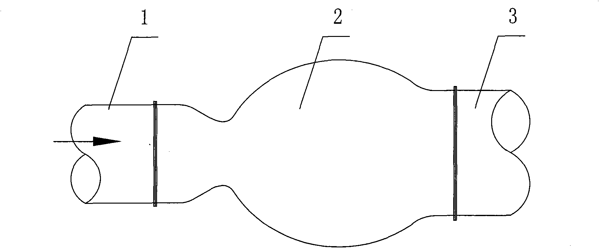
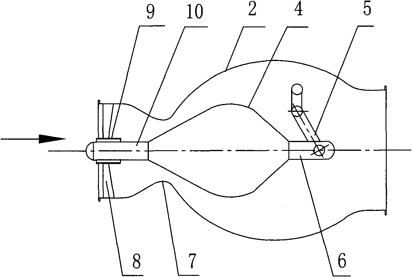
[0018] Such as figure 2 As shown, the blast furnace gas pressure reducing valve includes a valve body 2 and a valve core 4, the valve core 4 is located in the cavity of the valve body 2, and the inlet end and the outlet end of the valve body 2 are respectively provided with flanges for pipe connection; The part on the valve body 2 close to the inlet end of the valve body is the annular inner concave part 7 (that is, the annular inwardly concave part, which functions as a seal), and the valve core 4 is a double cone (both ends of the double cone are small head ends, The middle part has a large diameter, and the maximum diameter of the double cone is larger than the diameter of the annular inner recess; the cone of the double cone is sealed with the annular inner recess); one end of the valve core 4 is fixedly connected to one end of the first connecting rod 6 (also can be used Integral structure), the other end of the first connecting rod 6 is hinged with one end of the crank o...


PUM


Abstract

The invention relates to a blast furnace coal gas pressure reducing valve, which is used for a dry-method (wet method) dust removing system in the current ferrous metallurgy joint enterprises. The blast furnace coal gas pressure reducing valve comprises a valve body and a vale core, wherein the valve core is positioned in a cavity of the valve body; and flanges for connecting pipelines are respectively arranged at an inlet end and an outlet end of the valve body. The blast furnace coal gas pressure reducing valve is characterized in that the part close to the inlet end of the valve body on the valve body is an annular indent part; the valve core is a bipyramid; one end of the valve core is fixedly connected with one end of a first connecting rod; the other end part of the first connecting rod is hinged with one end part of a crankshaft of a crankshaft mechanism; one end of a rotating shaft of the crankshaft mechanism passes through a rotating shaft hole on the valve body and is positioned outside the valve body; the other end of the valve core is fixedly connected with one end of a sliding shaft; and the other end of the sliding shaft passes through a shaft sleeve which is positioned in the inlet end part of the valve body and is fixedly connected with the valve body through a supporting frame. The pressure reducing valve has the characteristics of noise reduction, pipeline vibration reduction and simple structure.

Description

technical field [0001] The invention relates to a blast furnace gas pressure reducing valve, which is used in the dry (wet) dust removal system of the blast furnace gas in the iron and steel metallurgical complex. Background technique [0002] At present, the technical characteristics of the blast furnace gas pressure reducing valve group are as follows: image 3 shown. [0003] Regardless of whether the blast furnace gas adopts the dry dust removal or wet dust removal process, when the TRT is not working, the static vane of the TRT is converted into a pressure reducing valve group to adjust and control the furnace top pressure. Because this system is safe and reliable, it has been used until now. [0004] However, the pressure reducing valve group adopted has the following defects: [0005] 1. Since the regulating element of the pressure reducing valve group is a valve plate, its air flow is not uniform, and when the high pressure gas is reduced to low pressure gas, the n...

Claims


Application Information

Patent Timeline
IPC IPC(8): F16K17/00F16L55/02
Inventor 祝建国田国庆夏朝晖
Owner WISDRI ENG & RES INC LTD
Why Eureka
Try Eureka