Driving mechanism and slip flask mold molding device in mold molding equipment

A driving mechanism, a technology of unboxing casting, which is used in casting and molding equipment, molding machines, equipment for loosening models, etc.

Active Publication Date: 2012-05-09
SINTOKOGIO LTD
View PDF0 Cites 0 Cited by
  • Summary
  • Abstract
  • Description
  • Claims
  • Application Information

AI Technical Summary

Problems solved by technology

[0005] However, in the mechanism described in Patent Document 2, there is the following problem: the piping system and the valve structure are complicated, and even with specialized knowledge and experience, assembly or maintenance also takes time
[0007] On the other hand, in the case of using electronic hydraulic machines in recent years, the initial cost of hydraulic units, hydraulic valves, hydraulic piping, etc. is high, and maintenance also requires specialized knowledge

Method used


Image

  • Driving mechanism and slip flask mold molding device in mold molding equipment
  • Driving mechanism and slip flask mold molding device in mold molding equipment
  • Driving mechanism and slip flask mold molding device in mold molding equipment

Examples


Embodiment 1

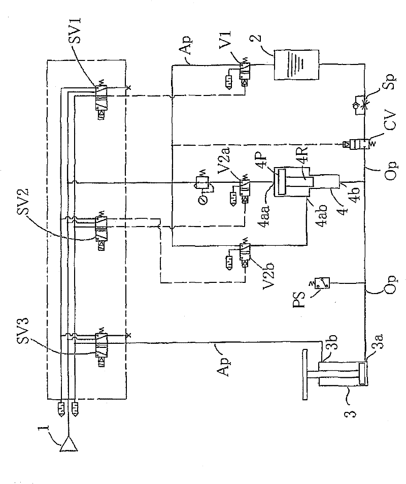
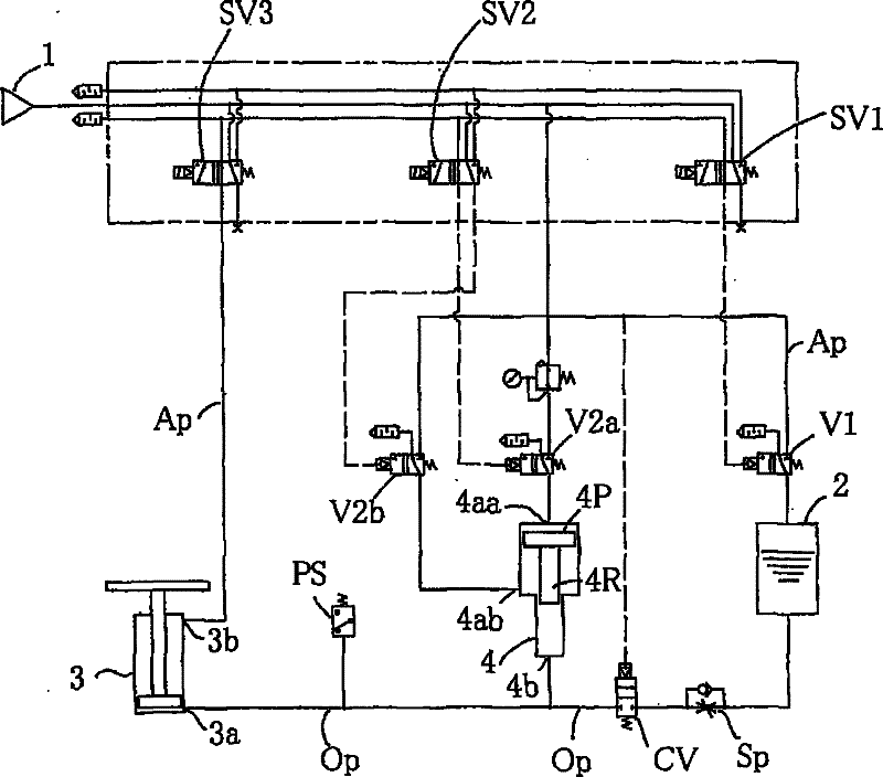
[0045] exist figure 1 Among them, the compressed air source 1 is a source that takes in compressed air or generates compressed air. One end of the upper portion of the oil tank 2 is connected to the compressed air source 1 in a communicable and disconnectable manner through an air pipe Ap. In order to enable communication and disconnection, a solenoid valve SV1 and a valve V1 operable by the solenoid valve SV1 are used. Furthermore, the lower part of the oil tank 2 is connected to the hole 3a (going hole) of the frame mounting squeeze cylinder 3 so that communication and disconnection are possible via hydraulic piping. Furthermore, the other hole 3b (return hole) of the frame housing squeeze cylinder 3 is connected to the compressed air source 1 in a communicable and disconnectable manner via the air pipe Ap.

[0046] Furthermore, the hole 4aa (going hole) and the hole 4ab (return hole) of the booster cylinder 4 are connected to the compressed air source 1 so that communica...

Embodiment 2

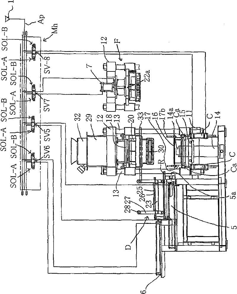
[0056] figure 2 It is a partial schematic piping system diagram of the drive mechanism of the present invention and a side view (including a partial front view) of the out-of-box mold molding device. In addition, in the driving mechanism, only a part of the air pressure piping is shown. exist figure 2 Among them, in the driving mechanism, the part of the driving frame where the extrusion cylinder 3 is placed can be the same as the embodiment 1, so this part is omitted. exist figure 2 Among them, the drive mechanism of the out-of-box mold molding device (hereinafter simply referred to as the out-of-box mold molding device) as sand molding equipment has a compressed air source 1 . Solenoid valves SV5 to SV8 utilizing air pressure are integrally connected with a compressed air source 1 via a manifold Mh. Furthermore, the compressed air source 1 and the mold ejection cylinder 5 are connected so as to be able to communicate and cut off via the solenoid valve SV5. Furthermor...

Embodiment 3

[0067] figure 2 It is a partial schematic piping system diagram of the drive mechanism of the present invention and a side view (including a partial front view) of the out-of-box mold molding device. In addition, only a part of the air pressure piping is shown. exist figure 2 In , the driving mechanism for driving the frame to place the extrusion cylinder 3 is the same as that in Embodiment 1, so this part is omitted.

[0068] exist figure 2 Among them, the door-shaped frame F is integrally connected with four-corner pillars 13 and 13 connecting the lower base frame 11 and the upper frame 12 . Frame placement extrusion cylinder 14 is installed on the upper surface central part of lower base frame 11 in the mode facing upwards, and lower pressing plate 16 is installed on the front end of the piston rod 14a of frame placement extrusion cylinder 14 through lower extrusion frame 15 . In addition, sliding bushes of at least 10 mm or more are provided at the four corners of t...


PUM


Abstract

The present invention provides a driving mechanism with the advantages of capacity for satisfying high-pressure extrusion, easy maintenance and miniaturization in the mold molding equipment, and a slip flask mold molding device with the driving mechanism. The driving mechanism comprises the following components: a compressed air source; an oil tank which has one end that is connected with the compressed air source with a mode that the connection can be switched off; a frame placement extrusion cylinder which has a return hole that is connected with the compressed air source with the mode that the connection can be switched off and has a going hole that is connected with the oil tank with the mode that the connection can be switched off through hydraulic piping; and a pressurizing cylinder. The going hole and the return hole of the pressurizing cylinder can be connected with the compressed air source with a mode that the connection can be switched off and are connected with the oil tank through a mode the communication is allowed. The pressurizing cylinder is connected with the frame placement extrusion cylinder with a normal communication mode through hydraulic piping. The slip flask molding device adopts the mechanism.

Description

technical field [0001] The invention relates to a driving mechanism in sand molding equipment. More specifically, it relates to a drive mechanism that uses air pressure and a booster cylinder to boost the air pressure without using a hydraulic unit, and converts the air pressure into high hydraulic pressure to operate a pressing mechanism, and a drive mechanism using the same. Out of box casting molding device. Background technique [0002] Conventionally, air pressure and hydraulic pressure have been used to drive the mold molding equipment for making molds. In addition, documents related to this are also known (for example, refer to Patent Document 1). [0003] However, conventional molding devices that use two types of drive, namely pneumatic drive and hydraulic drive, have the following problems. First, a hydraulic unit is required for hydraulic drive, and the initial cost of a hydraulic pump, a hydraulic valve, and the like is high. In addition, in the pneumatic dri...

Claims


Application Information

Patent Timeline
Patent Type & Authority Patents(China)
IPC IPC(8): B22C19/04B22C19/06B22C15/08
Inventor 波多野丰小宫山贵之高须修司井出修一新田拓也
Owner SINTOKOGIO LTD
Why Eureka
Try Eureka