Supercharge Your Innovation With Domain-Expert AI Agents!

Method of radially expanding a tubular element

A technology of tubular components and expansion tubes, which is applied in earthwork drilling, wellbore/well components, production fluids, etc., and can solve problems such as the risk of tube expander stuck

Inactive Publication Date: 2013-06-12
SHELL INT RES MAATSCHAPPIJ BV
View PDF7 Cites 0 Cited by
  • Summary
  • Abstract
  • Description
  • Claims
  • Application Information

AI Technical Summary

Problems solved by technology

Also, there is a risk of the expander getting stuck in the tubular element

Method used


Image

  • Method of radially expanding a tubular element
  • Method of radially expanding a tubular element
  • Method of radially expanding a tubular element

Examples


Embodiment Construction

[0036] In the drawings and the description, like numerals refer to like parts.

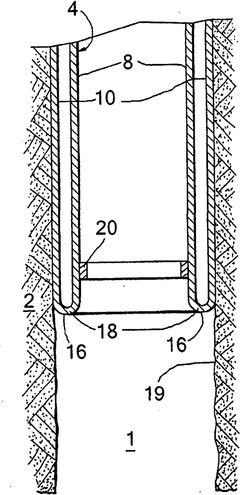
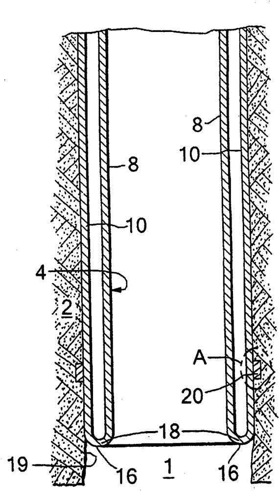
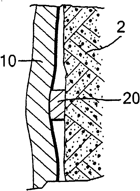
[0037] refer to Figure 1-3 , shows a longitudinal section of a first embodiment comprising a wellbore 1 extending into the formation 2 and a tubular element in the form of a liner 4 extending down into the wellbore 1 . The liner 4 has been partially radially expanded by eversion of the liner wall, thereby forming a radially expanded tubular portion 10 of the liner 4 having an outer diameter substantially equal to the borehole diameter. The remaining tubular portion 8 of the liner 4 extends concentrically within the expanded tubular portion 10 .

[0038] The wall portion of the liner 4 , due to its lower end everted, extends radially outward and axially in the opposite (ie upward) direction to form a U-shaped lower portion of the liner interconnecting the remaining liner portion 8 and the expanded liner portion 10 16. The U-shaped lower part 16 of the liner 4 defines a bending zone 18 of the li...


PUM


Abstract

A method is provided of radially expanding a tubular element extending into a wellbore formed in an earth formation, the method comprising inducing the wall of the tubular element to bend radially outward and in axially reverse direction so as to form an expanded tubular section extending around a remaining tubular section of the tubular element, wherein said bending occurs in a bending zone of the tubular element, and increasing the length of the expanded tubular section by inducing the bending zone to move in axial direction relative to the remaining tubular section. One of the tubular element and the wellbore wall is provided with at least one seal member arranged to induce sealing of the expanded tubular section relative to the wellbore wall.

Description

technical field [0001] The present invention relates to a method of radially expanding a tubular element in a wellbore. Background technique [0002] The technique of radially expanding tubular elements in the wellbore is increasingly used in the oil and gas production industry from subterranean formations. The wellbore is typically provided with one or more casings or liners to provide stability to the wellbore wall and / or to provide reservoir isolation between different formations. The terms "casing" and "liner" refer to tubular elements used to support and stabilize the walls of a wellbore, and it is generally understood that the casing extends from the surface into the wellbore and the liner extends further into the wellbore from a downhole location. However, in this document, the terms "casing" and "liner" are used interchangeably and there is no such tendentious distinction. [0003] In conventional wellbore configurations, several casings are set at different depth ...

Claims


Application Information

Patent Timeline
Patent Type & Authority Patents(China)
IPC IPC(8): E21B43/10
CPCE21B43/103
Inventor F·J·侯P·C·克里塞尔斯P·范尼乌库普
Owner SHELL INT RES MAATSCHAPPIJ BV
Features
  • R&D
  • Intellectual Property
  • Life Sciences
  • Materials
  • Tech Scout
  • Unparalleled Data Quality
  • Higher Quality Content
  • 60% Fewer Hallucinations
Learn More