Air duct type electronic air purification machine

An electronic air and purifier technology, which is applied in the separation of dispersed particles, chemical instruments and methods, separation methods, etc., can solve the problems of plasma concentration reduction, achieve the effects of degrading TVOC, eliminating odors, and efficiently killing bacteria

Active Publication Date: 2010-12-22
ZHEJIANG TIANQING ENVIRONMENTAL PROTECTION TECH CO LTD
View PDF2 Cites 7 Cited by
  • Summary
  • Abstract
  • Description
  • Claims
  • Application Information

AI Technical Summary

Problems solved by technology

This decline phenomenon is imperceptible, and the decrease...

Method used


Image

  • Air duct type electronic air purification machine
  • Air duct type electronic air purification machine
  • Air duct type electronic air purification machine

Examples


Embodiment 1

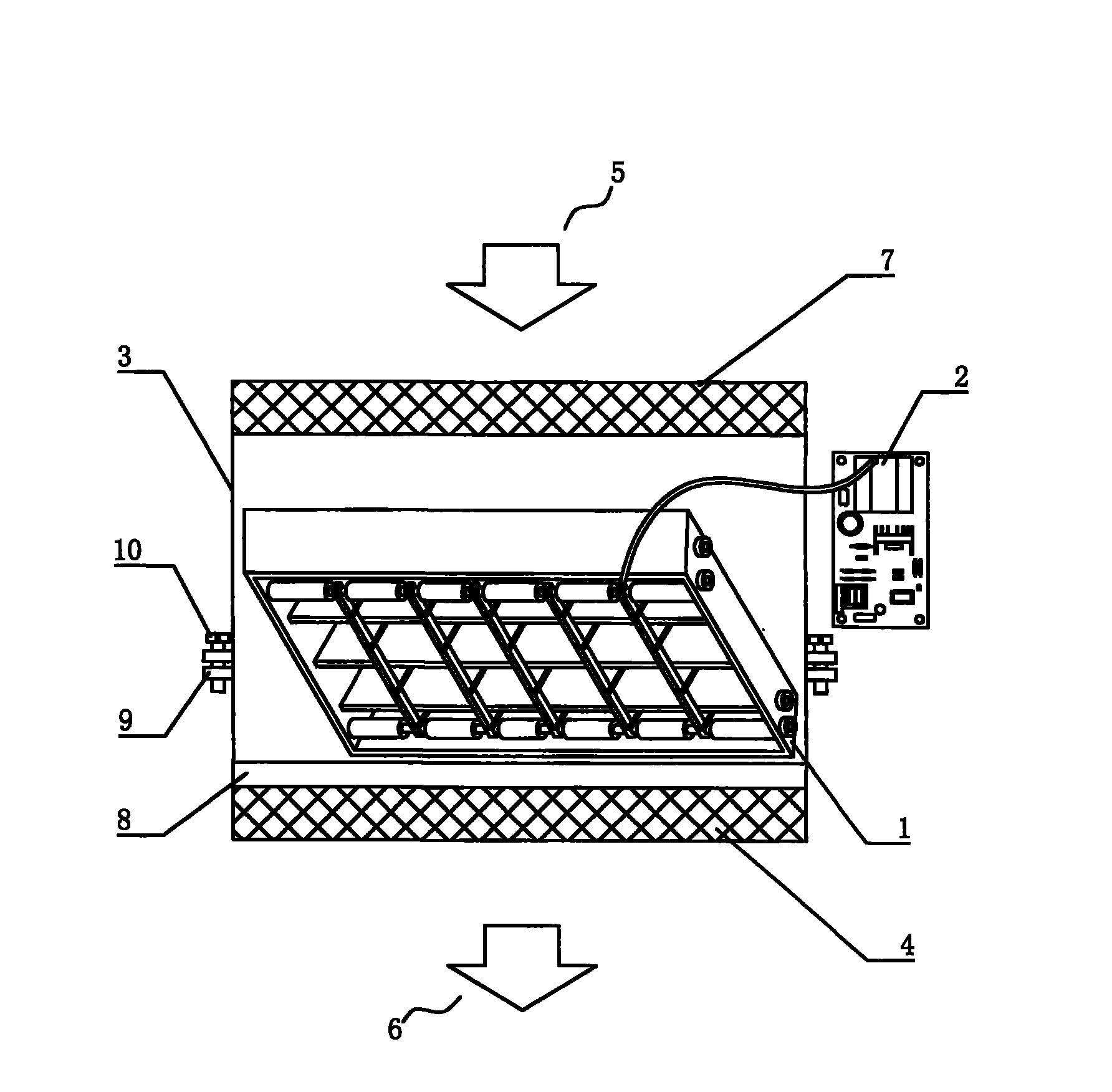
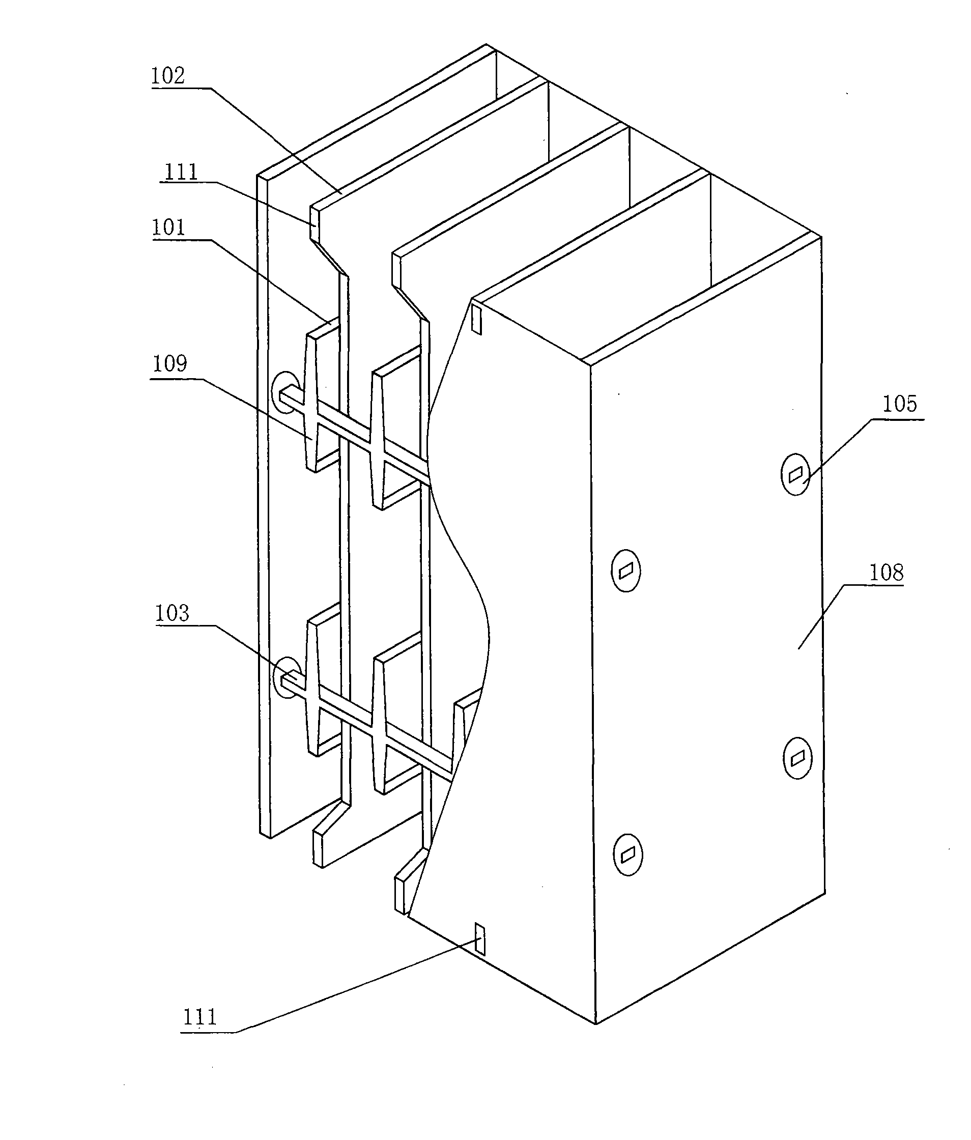
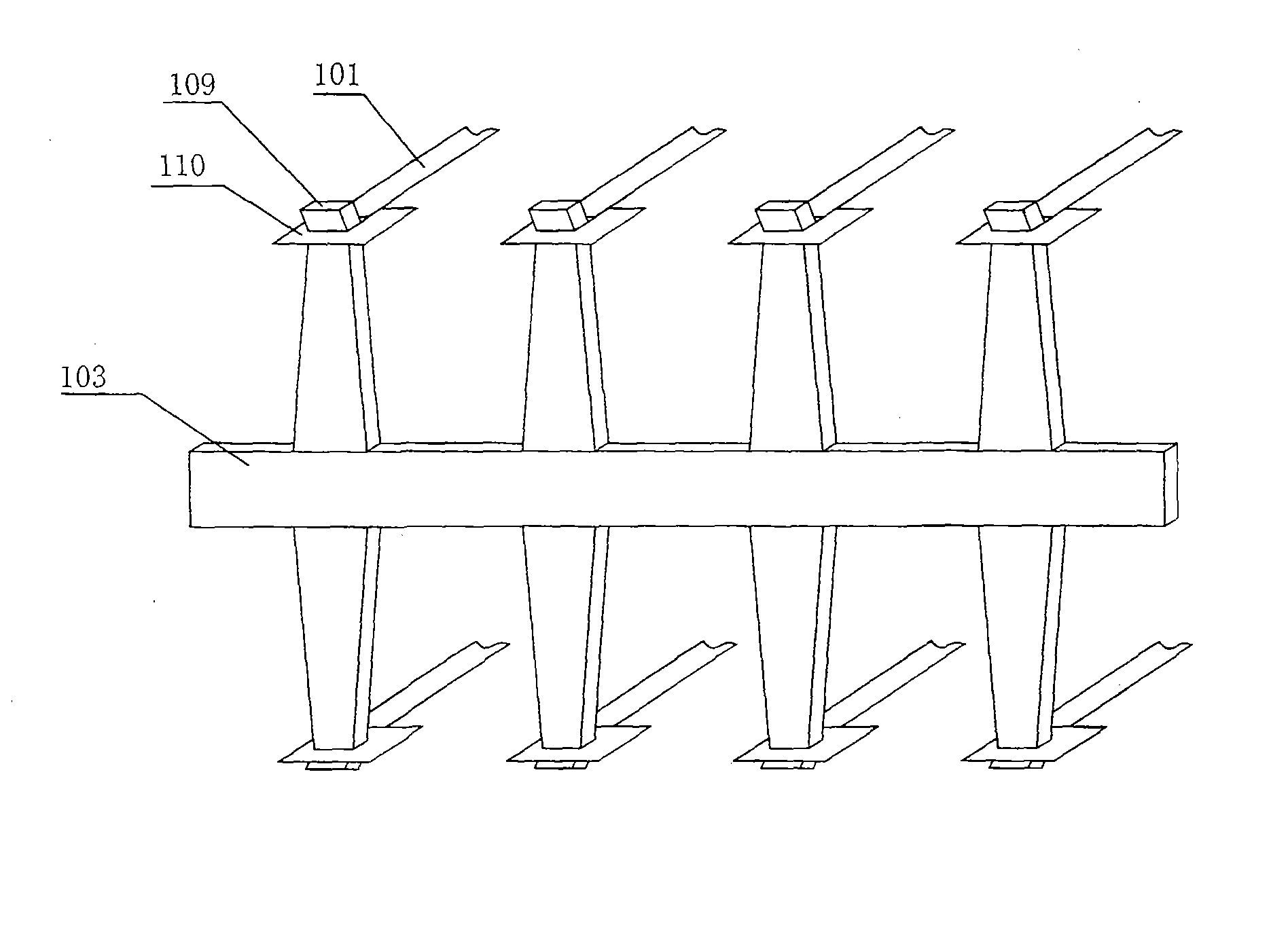
[0047] figure 1 It is a structural schematic diagram of the air duct type electronic air purifier of the present invention; figure 2 It is a three-dimensional structure diagram of a plasma reactor half section of the present invention; image 3 yes figure 2 Schematic diagram of the conductive rail structure for preventing microdischarge.

[0048] As shown in the figure, the plasma air disinfection and purification air conditioner includes 1. Air duct type electronic air cleaner, including plasma reactor 1, pulse power supply 2, air inlet 5 with air inlet air filter 7, and air outlet 6 with Air outlet air filters 4 are all installed in the casing 3 . The plasma reactor 1 is arranged on the wind deflector 8, the high voltage output end of the pulse power supply 2 is electrically connected with the plasma reactor 1, and the plasma reactor 1 is arranged in the air flow duct. The described plasma reactor 1 is provided with a positive electrode 101 and a negative electrode 102...

Embodiment 2

[0052] The micro-discharge conductive rail 103 of the present invention is provided with convex portions 109 arranged equidistantly, and the two ends of the positive electrode 101 are the tops of the convex portion 109 respectively fixed on the corresponding conductive rail; the convex portion of the micro-discharge conductive rail 103 is prevented 109 are set as one group of two up and down symmetrical ones, and n groups are set up for each convex portion 109 that prevents the micro-discharge conductive rail 103, and the top of the convex portion 109 is provided with an outward bend. The two ends of the positive electrode 101 are provided with a stainless steel connection frame 110 , and a square hole is punched in the middle of the stainless steel connection frame 110 . A protruding negative electrode fixing pin 111 is provided on the upper and lower ends of the negative electrode 102 adjacent to the reactor shell 108, and the corresponding part of the reactor shell 108 is pr...

Embodiment 3

[0056] Figure 4 It is a three-dimensional structure diagram of another embodiment of the plasma reactor of the present invention. As shown in the figure, the described anti-micro-discharge conductive rail 103 is provided with recesses arranged equidistantly, and the concave portions are provided with n groups. The two ends of the micro-discharge conductive rail 103 are fixed and electrically connected with four positive electrode metal supports 104 which are orthogonally arranged around the reactor; Discharge conductive rail fixed ring 107, prevent micro-discharge conductive rail fixed ring 107 from equidistantly adjacent to prevent micro-discharge conductive rail 103; each positive electrode metal support 104 is provided with an insulating connector 105 and two ends respectively. The corresponding mounting holes of the housing 108 are fixed. An insulating connector fixing bolt 106 is provided to fasten the insulating connector 105 on the metal reactor shell 108 .

[0057] T...


PUM

PropertyMeasurementUnit
Widthaaaaaaaaaa
Thicknessaaaaaaaaaa
Band gap energyaaaaaaaaaa

Abstract

The invention relates to an air duct type electronic air purification machine, belonging to the field of air sterilization and purification technologies. The air purification machine comprises a plasma reactor, a pulse power source, an air inlet and an air outlet. A positive electrode and a negative electrode are arranged in the plasma reactor, wherein the positive electrode is made of an oxidation resisting metal strap, the negative electrode is made of an aluminum plate or a stainless steel plate, and both faces of the negative electrode are coated with TiO2. A micro discharge preventing conductor rail made of an aluminum bar or a stainless steel bar is also arranged, and both ends of the positive electrode are fixed on relative positions on the micro discharge preventing conductor rail. The air purification machine can kill bacteria and viruses, degrade organic compounds and remove particulate pollutants, the produced plasma has high concentration, ozone and oxynitride have low concentration without secondary pollution, and the sterilization effect is doubled. Moreover, the invention has the advantages of simple structure, energy saving, high reliability and long service life. The air purification machine is installed in an air duct of a central air-conditioning system and used for the air sterilization and purification of places such as hospitals, clean rooms, office buildings, shopping malls, hotels, theatres, airports, subways, and the like.

Description

Technical field: [0001] The invention belongs to the technical field of air disinfection and purification, and in particular relates to an air duct type electronic air purifier. Background technique: [0002] The air duct type electronic air purifiers currently on the market are installed in the air duct of the centralized air conditioning system, and some are installed at the air return port or the air supply port to purify the air in the room through circulation. They generally consist of metal filters, high-voltage ionizers, dust collection chambers, cold catalyst filters excited by ultraviolet lamps, and granular activated carbon filters. Most of the "heavy" particles are filtered through the electronic air cleaner's metal filter. Smaller particles are ionized by a high voltage as they enter the ionization zone with the airflow—giving them a positive charge. When the positively charged particles pass through the negatively charged dust collecting plate (output DC high ...

Claims


Application Information

Patent Timeline
IPC IPC(8): A61L9/22B01D53/86A61L101/02
Inventor 周云正周瑾
Owner ZHEJIANG TIANQING ENVIRONMENTAL PROTECTION TECH CO LTD
Why Eureka
Try Eureka