Energy storage system and control method thereof

An energy storage system and controller technology, applied in the direction of AC network load balancing, etc., can solve the problems of limited boosting capacity of boost converters, increase the total harmonic content of output current, and inapplicability, and achieve a wide range of applications, avoidance of Mutual interference and high utilization effect

Inactive Publication Date: 2011-01-12
BEIJING INSTITUTE OF TECHNOLOGYGY
View PDF5 Cites 19 Cited by
  • Summary
  • Abstract
  • Description
  • Claims
  • Application Information

AI Technical Summary

Problems solved by technology

Power factor correction can be done, but the buck inverter requires the bus voltage to be higher than the AC output voltage, so this topology is not suitable for low-voltage energy storage devices, such as supercapacitors
And there is no electrical isolation between the grid and the energy storage device
IEEE Trans.on Power Electronics [Journal of Power Electronics] published the article "Three-Phase Boost-Type Grid-Connected Inverter" [Thre

Method used


Image

  • Energy storage system and control method thereof
  • Energy storage system and control method thereof
  • Energy storage system and control method thereof

Examples


Embodiment Construction

[0022] In order to make the above objects, features and advantages of the present invention more comprehensible, the present invention will be further described in detail below in conjunction with the accompanying drawings and specific embodiments.

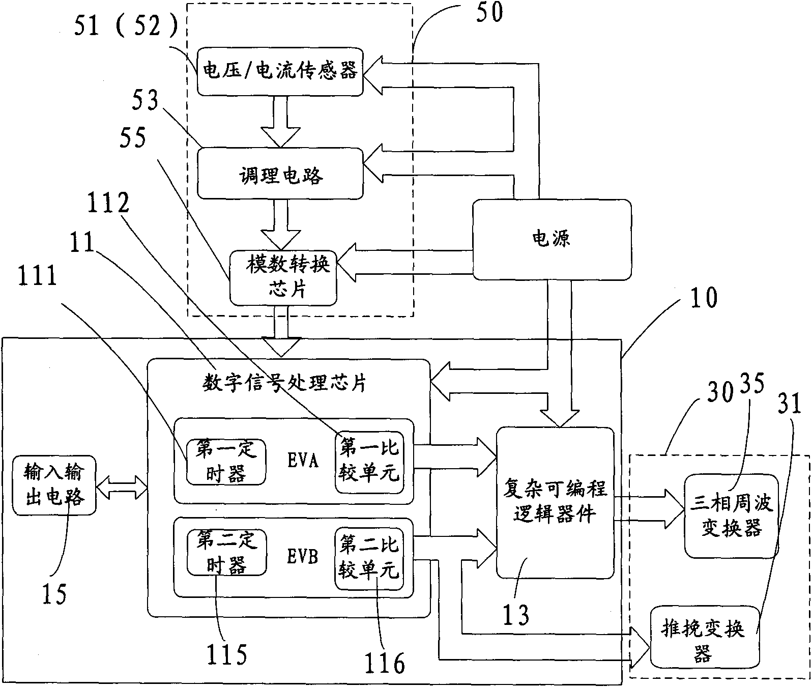
[0023] Please refer to figure 1 , shows an energy storage system, including a controller 10 , a main circuit 30 and a sampling circuit 50 .

[0024] The controller 10 includes a digital signal processing chip 11 , a complex programmable logic device 13 , a general input and output circuit 15 and a switch driving circuit. The digital signal processing chip 11 includes an event manager module EVA and an event manager module EVB. EVA includes a first timer 111 and a first comparison unit 112 , and EVB includes a second timer 115 and a second comparison unit 116 . The first timer 111 and the first comparison unit 112 are used to generate SVPWM (Space Vector Pulse Width Modulation, Space Vector Pulse Width Modulation), and the first ...


PUM


Abstract

The invention provides an energy storage system which comprises a controller, a main circuit, a push-pull converter, a cycloconverter, a filter inductor and a sampling circuit. The controller is used for controlling the generation of an SVPWM (Space Vector Pulse Width Modulation) signal and a PWM (Pulse Width Modulation) signal to obtain a discrete SVPWM signal, the main circuit comprises an energy storage device for storing and releasing electric energy, the push-pull converter comprises a high-frequency transformer and is boosted by adopting the high-frequency transformer to electrically isolate the input from the output of the energy storage system, the cycloconverter is used for converting a high-frequency alternating voltage into a power frequency alternating voltage, the filter inductor is used for filtering a grid current, and the sampling circuit is used for acquiring a voltage and a current of an external circuit. The energy storage system can generate discrete pulse-type SVPWM and has the advantages of higher utilization rate of the bus voltage, low total harmonic content and wide scope of application. The invention also provides a control method of the energy storage system.

Description

technical field [0001] The present invention relates to an energy storage system and a control method, in particular to an energy storage system and a control method for peak-shaving and valley-filling of a power grid. Background technique [0002] With the development of power electronics technology, energy storage systems are used more and more widely, such as uninterruptible power supply (UPS), electric vehicles, and energy storage devices for power grid shaving and filling valleys. The energy storage device stores electric energy during low power consumption periods (charging), and releases electric energy to support the grid during peak power consumption periods (discharging). In order to achieve the effect of peak shaving and valley filling, the converter between the energy storage device and the grid must not only have two-way conversion capability, but also require a fast response to the conversion and a unit power factor of the system. [0003] The patent "energy s...

Claims


Application Information

Patent Timeline
IPC IPC(8): H02J3/28
Inventor 沙德尚秦子安廖晓钟
Owner BEIJING INSTITUTE OF TECHNOLOGYGY
Why Eureka
Try Eureka