Retroreflective pavement markings
A road marking, complete technology, applied in road signs, roads, roads, etc., can solve problems such as unsatisfactory retroreflection performance
- Summary
- Abstract
- Description
- Claims
- Application Information
AI Technical Summary
Problems solved by technology
Method used
Image

Examples
preparation example Construction
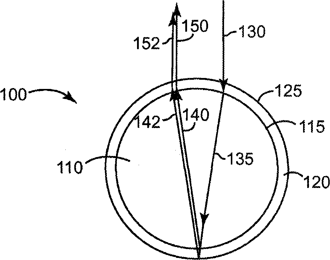
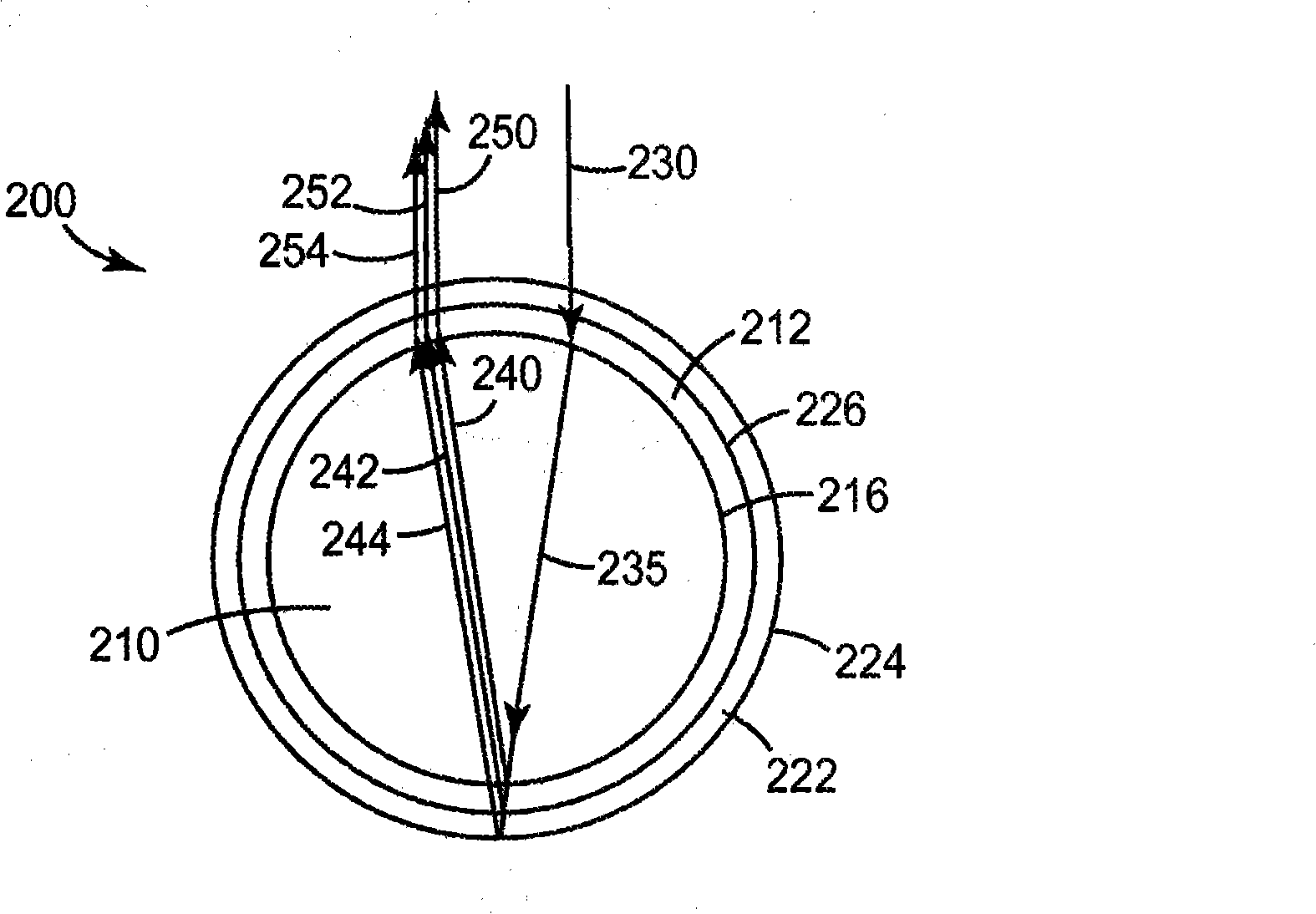
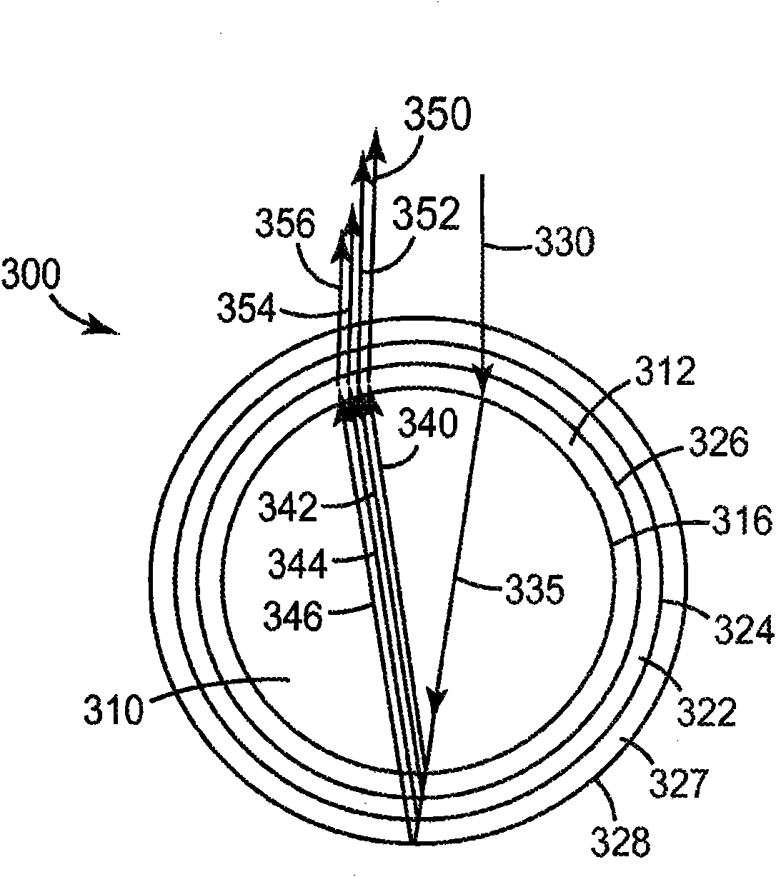
[0085] Preparation of retroreflective elements
[0086] The retroreflective elements can be prepared conveniently and economically using fluidized bed and vapor deposition techniques of transparent beads. In general, as used herein, the process of depositing a vapor-phase material onto a fluidized (i.e., agitated) bed of multiple beads may collectively be referred to as a "vapor-phase deposition process" in which concentric layers are deposited from a vapor form on the surface of each transparent bead . In some embodiments, the gas phase precursor materials are mixed in the vicinity of the transparent beads and chemically reacted in situ to deposit layers of materials on the respective surfaces of the transparent beads. In other embodiments, the material is present in vapor form and deposited as a layer on the respective surfaces of the transparent beads substantially without chemical reaction.
[0087] Depending on the deposition process used, the precursor material (in t...
example
[0129] Use the standard procedure below.
[0130] Process A: Preparation of Retroreflective Elements
[0131] Coating of metal oxide (titanium dioxide or silicon dioxide) by utilizing atmospheric pressure chemical vapor deposition (APCVD) similar to that described in U.S. Patent No. 5,673,148 (Morris et al.), the disclosure of which is incorporated herein by reference. Deposited on a clear bead core to form a retroreflective element with an integral concentric optical interference layer. The inner diameter of the reactor was 30 mm. The initial charge of clear beads weighed 60 g. For the silica coating, the reaction temperature was set at 40°C, while a reaction temperature of 140°C was used to deposit the titania coating. The desired reaction temperature was controlled by immersing the reactor in a heated oil bath maintained at a constant temperature. The bed of beads was fluidized with a nitrogen flow introduced into the reactor through the base of the glass frit reactor...
example 45-69
[0149] Examples 45-69 used Type I bead cores. Coated retroreflective elements were prepared according to Procedure A such that the coated retroreflective elements included two concentric optical interference layers. Examples 45-60 were prepared using Type I bead cores coated with an inner or first optical interference layer of silica and an outer or second optical interference layer of titania. Examples 61-69 were prepared from Type I bead cores and coated with an inner or first optical interference layer of titania and an outer or second optical interference layer of silica. The coating material, thickness and retroreflective brightness (Ra) of the clear patch construction are reported in Table 3.
[0150] table 3
[0151]
[0152] According to Procedure C, the retroreflected color of Examples 45, 47, 49, 50, 52, 54, and 55 was estimated. Table 3A lists the color coordinates, the observed color, the distance from the black body radiation curve between 4800K and 7500K,...
PUM
| Property | Measurement | Unit |
|---|---|---|
| The average diameter | aaaaa | aaaaa |
| Refractive index | aaaaa | aaaaa |
Abstract
Description
Claims
Application Information