
Front-end circuit, tuner, and television broadcasting receiver
A circuit and control circuit technology, applied in the field of frequency control of the local oscillator signal, can solve problems such as the saturation of the latter stage circuit
- Summary
- Abstract
- Description
- Claims
- Application Information
AI Technical Summary
Problems solved by technology
Method used
Image

Examples
Embodiment approach 1
[0068] Below, according to Figure 1 to Figure 5 Embodiment 1 of the present invention will be described.
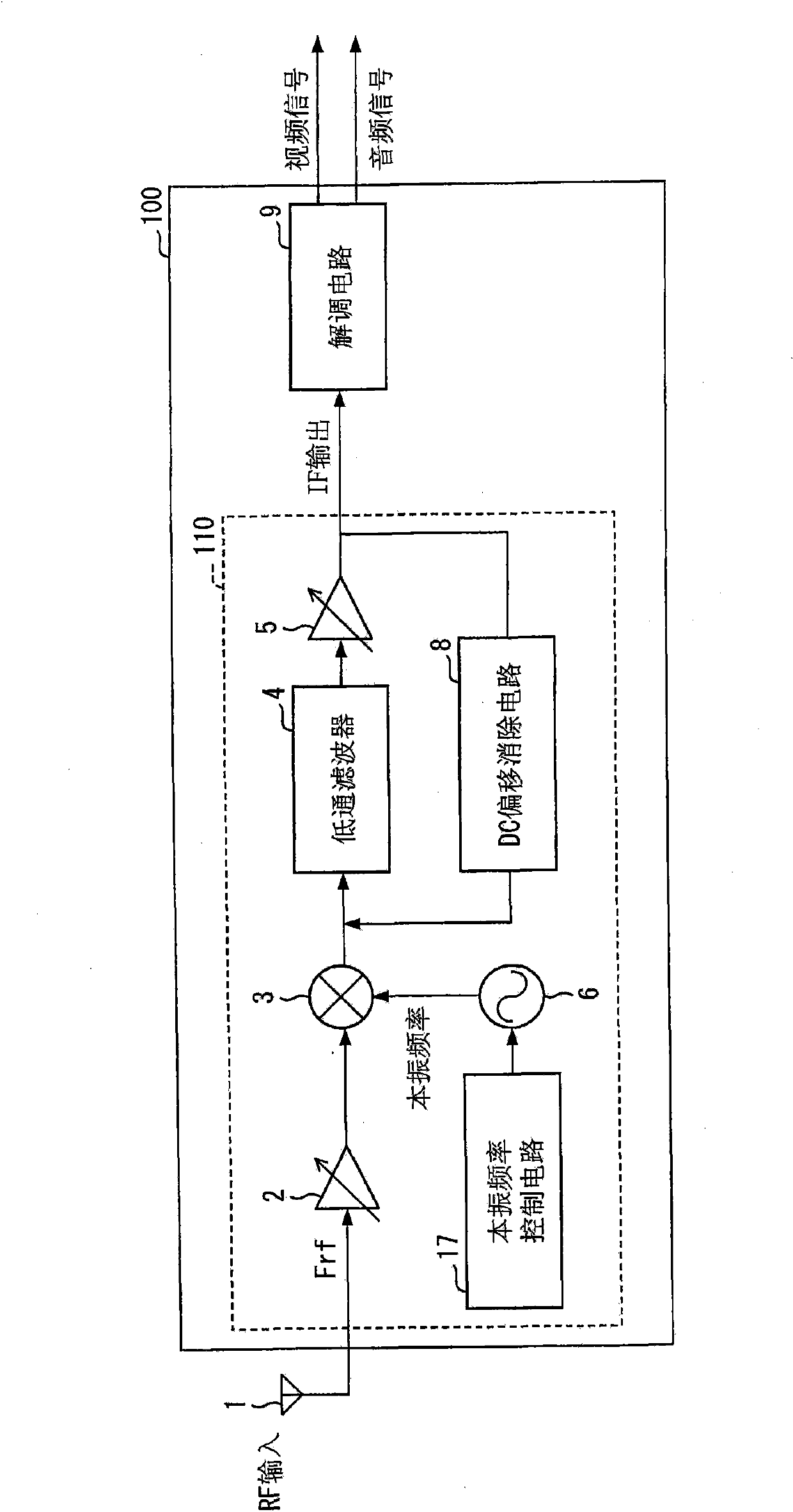
[0069] figure 1 It is a block diagram showing the configuration of the tuner 100 of this embodiment. Tuner 100 is the Figure 10 The front-end circuit 410 in the tuner 400 of the prior art shown is replaced with the front-end circuit 110. The front-end circuit 110 is configured by replacing the local oscillator frequency control circuit 7 in the front-end circuit 410 with the local oscillator frequency control circuit 17 . In this embodiment, for the convenience of description, the Figure 10 Components of the shown tuner 400 having the same functions are given the same symbols, and descriptions of these components are omitted.
[0070] In addition to the function of the local oscillator frequency control circuit 7 in the prior art, the local oscillator frequency control circuit 17 also has the following functions, that is: the frequency of the local signal is contro...
Embodiment approach 2
[0092] The following is based on Figure 6 to Figure 8 Embodiment 2 of the present invention will be described. Regarding the local signal from VCO6, it is ideal that there is no error between the frequency of the local signal set and the frequency actually output. However, as for the reference signal used by the local oscillator frequency control circuit 17 for frequency control, if a crystal resonator is used as a reference oscillator for generating the reference signal, since the reference signal has a frequency deviation, there may be differences in the local signal. Frequency error between desired frequencies. On the other hand, in this embodiment, the frequency control of the local signal in consideration of the frequency error of the local signal will be described.
[0093] Figure 6 It is a block diagram showing the configuration of the tuner 200 of this embodiment. Tuner 200 is the figure 1 The front-end circuit 110 in the tuner 100 of the prior art shown is rep...
Embodiment approach 3
[0113] The following is based on Figure 9 Embodiment 3 of the present invention will be described.
[0114] Figure 9 It is a block diagram of the structure of the television broadcast receiver 300 of this embodiment. Television broadcast receiver 300 receives RF signals from antenna 310 and antenna 311, and includes tuner 320 / 321, switch 330 / 331, video signal processing circuit 340, audio signal processing circuit 341, display device 350, speaker 351, system control device 360, key output unit 370, and remote control input unit 380.
[0115] The RF signals received from the antennas 310 / 311 are respectively sent to the tuners 320 / 321, and the tuners 320 / 321 convert the RF signals into IF signals and demodulate the IF signals into video signals and audio signals. The video signal from the tuner 320 / 321 is output to the switch 330, and the audio signal from the tuner 320 / 321 is output to the switch 331.
[0116] The switch 330 selects a signal to be output to the video sig...
PUM
 Abstract
Description
Claims
Application Information