Direct current offset calibration system and method

A technology of DC offset and calibration system, applied in control/regulation system, transmission system, adjusting electrical variables, etc., can solve the problem of low-pass filter circuit occupying device area, affecting the working speed of high-speed receiver circuit, etc., to eliminate DC effect of dissonance

Active Publication Date: 2022-02-18
SIGMASTAR TECH LTD
View PDF6 Cites 0 Cited by
  • Summary
  • Abstract
  • Description
  • Claims
  • Application Information

AI Technical Summary

Problems solved by technology

Reduce the offset error by directly increasing the device area. Although this method is simple, it will affect the working speed of the high-speed receiver circuit.
The method of adding an analog auxiliary circuit is to use a low-pass filter to first filter out the high-frequency component of the signal to obtain a DC level to control and eliminate the DC offset, but the disadvantage is that the low-pass filter circuit also needs to occupy the device area, and it will also affect the high-speed The working speed of the receiver circuit

Method used


Image

  • Direct current offset calibration system and method
  • Direct current offset calibration system and method
  • Direct current offset calibration system and method

Examples


Embodiment Construction

[0028] Below in conjunction with accompanying drawing, structural principle and working principle of the present invention are specifically described:

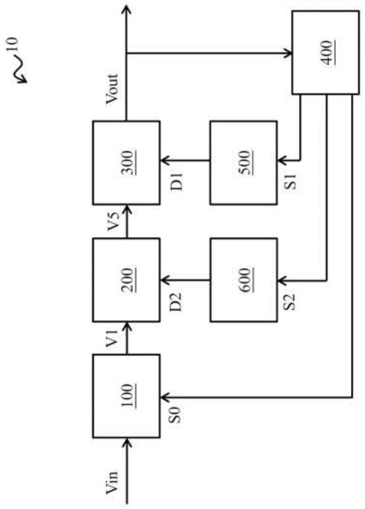
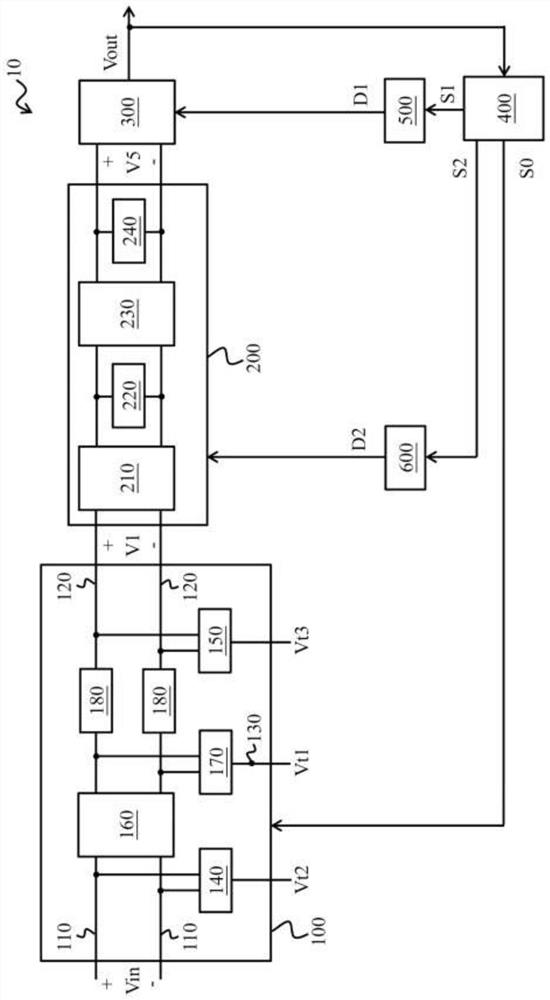
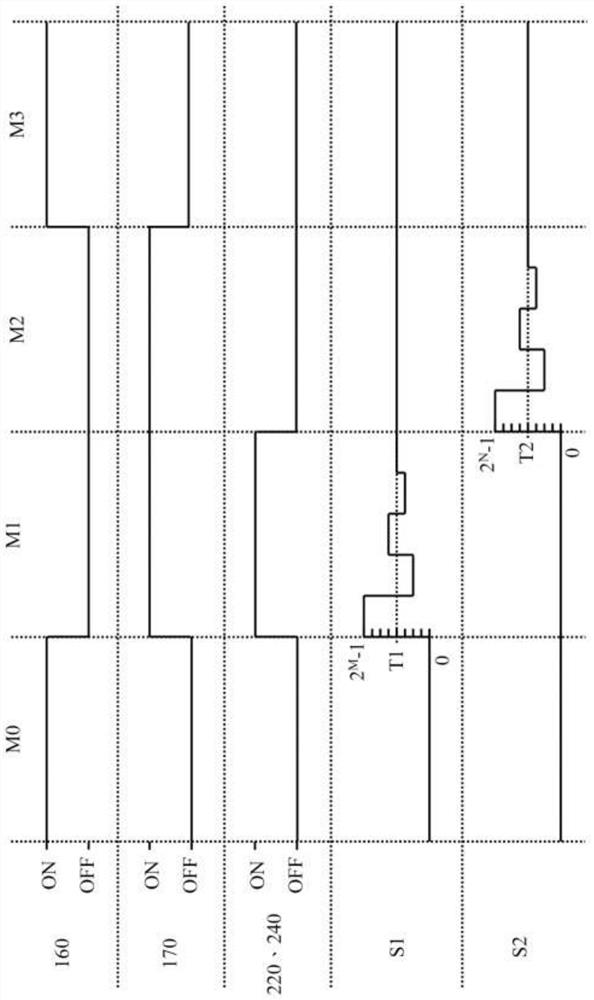
[0029] figure 1 is a schematic block diagram of a DC offset calibration system 10 according to some embodiments of the present invention, figure 2 is a schematic circuit diagram of a DC offset calibration system 10 according to some embodiments of the present invention, image 3 It is a timing diagram of the DC offset calibration system 10 of some embodiments of the present invention. Please also see figure 1 , figure 2 and image 3 , in some embodiments, the DC offset calibration system 10 is arranged at the receiver end to process the differential input signal Vin, and the DC offset calibration system 10 is suitable for operating in one of the working mode M3, the first calibration mode M1 and the second calibration M2 mode . The DC offset calibration system 10 includes a matching circuit 100 , an equalization circui...


PUM


Abstract

The invention provides a direct current offset calibration system and method. The system is arranged at a receiver end to process differential input signals and operates in one of a working mode, a first calibration mode and a second calibration mode. The system comprises a matching circuit, an equalization circuit, an amplification circuit, a control circuit, a first digital-to-analog conversion circuit and a second digital-to-analog conversion circuit, wherein the equalization circuit is electrically connected with the matching circuit, the amplification circuit is electrically connected with the equalization circuit, and the control circuit is electrically connected with the amplification circuit. In the operating mode, the matching circuit provides impedance matching for the differential input signal. A first digital signal and a second digital signal are respectively output in the first calibration mode and the second calibration mode. The first digital-to-analog conversion circuit and the second digital-to-analog conversion circuit respectively generate a first differential calibration signal and a second differential calibration signal according to the first digital signal and the second digital signal. In the first calibration mode, the amplification circuit generates a first amplification signal according to the first differential calibration signal, and feeds back and adjusts the first digital signal; and in the second calibration mode, the equalization circuit and the amplification circuit generate a second amplification signal according to the second digital signal, and feed back and adjust the second digital signal.

Description

technical field [0001] The invention relates to the field of DC offset calibration, in particular to a DC offset calibration system and method thereof. Background technique [0002] With the continuous advancement of integrated circuit technology, high-speed serial communication technology has been further developed. However, with the increase of clock speed and various unideal factors in transmission (such as transmission line loss, process deviation), it will cause high-speed reception. The transmission performance of the terminal circuit is degraded, and even the requirements of the high-speed data transmission protocol cannot be met. In view of the above situation, it is necessary to add terminal matching circuit, equalization circuit and sense amplifier to the high-speed receiver circuit to overcome it, but adding these circuits also introduces process deviation and DC offset error, so it is very important to eliminate these errors. At present, the technology of elimin...

Claims


Application Information

Patent Timeline
Patent Type & Authority Applications(China)
IPC IPC(8): G05F3/26
CPCG05F3/26H04B1/1615H04B17/21
Inventor 李健孙凯
Owner SIGMASTAR TECH LTD
Why Eureka
Try Eureka