Current preamplifier, time-resolved readout circuit and time-resolved detection device

A preamplifier and current amplification technology, applied in the field of nuclear detection technology and nuclear electronics, can solve the problems that NINO chips can not meet the experimental requirements, limit the application of NINO chips, and the noise of the preamplifier is high, so as to ensure accurate identification and low noise. Equivalent input impedance, effect of stable output baseline voltage

Active Publication Date: 2019-05-10
INST OF HIGH ENERGY PHYSICS CHINESE ACAD OF SCI
View PDF5 Cites 0 Cited by
  • Summary
  • Abstract
  • Description
  • Claims
  • Application Information

AI Technical Summary

Problems solved by technology

In the NRS experiment, with 57 Fe nuclear resonance scattering is taken as an example, the X-ray energy is 14.4keV, the magnification of the APD sensor is M=50, and the nuclear scattering signal generated is about 32fC. Therefore, the NINO chip cannot meet the experimental requirements; (2) The NINO chip is only suitable for parasitic Sensors with capacitance < 10pF, which limits the application of NINO chips in many synchrotron radiation time-resolved experiments
In order to improve the experimental efficiency, APD sensors with large photosensitive areas are usually used in time-resolved experiments such as synchrotron radiation NRS and IXS. Area 10mm×10mm, parasitic capacitance 120pF), the NINO chip cannot read the signal of this kind of large parasitic capacitance APD sensor
[0004] Therefore, it is necessary to solve the problem that the current preamplifier used in the existing time-resolved readout circuit chip has large noise and is only suitable for sensors with parasitic capacitance <10pF, so as to meet the experimental requirements

Method used

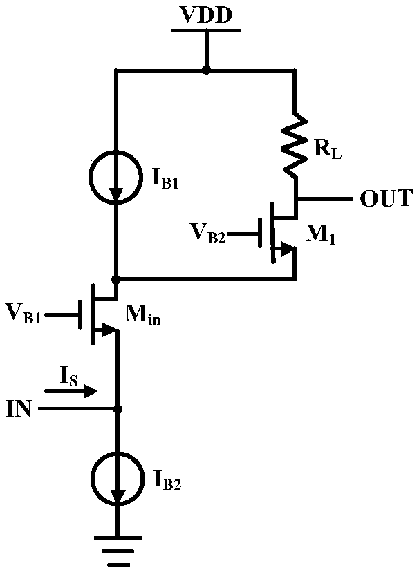

Image

  • Current preamplifier, time-resolved readout circuit and time-resolved detection device
  • Current preamplifier, time-resolved readout circuit and time-resolved detection device
  • Current preamplifier, time-resolved readout circuit and time-resolved detection device

Examples


Embodiment Construction

[0043]Example embodiments will now be described more fully with reference to the accompanying drawings. Example embodiments may, however, be embodied in many forms and should not be construed as limited to the examples set forth herein; rather, these embodiments are provided so that this disclosure will be thorough and complete and will fully convey the concept of example embodiments to those skilled in the art. The described features, structures, or characteristics may be combined in any suitable manner in one or more embodiments. In the following description, numerous specific details are provided in order to give a thorough understanding of embodiments of the present disclosure. However, those skilled in the art will appreciate that the technical solutions of the present disclosure may be practiced without one or more of the specific details being omitted, or other methods, components, devices, steps, etc. may be adopted. In other instances, well-known technical solutions...


PUM


Abstract

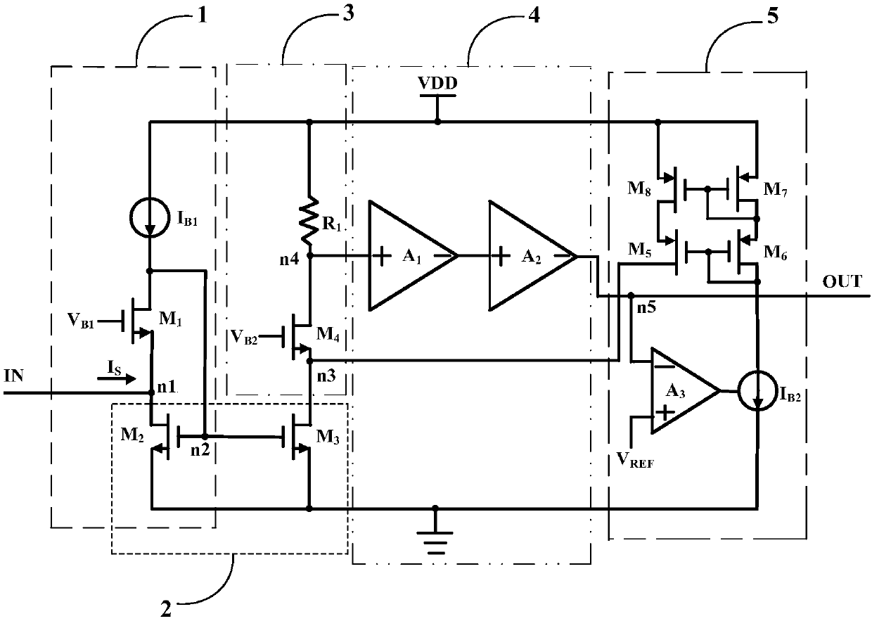
The invention relates to a current pre-amplifier, a time resolution reading circuit and a time resolution detection device. The current pre-amplifier comprises a current input module which is used for receiving and outputting current signals; a current amplifier module which is used for receiving the current signals output by the current input module, amplifying the current signals and then outputting the current signals; a current to voltage conversion module which is used for receiving the current signals output by the current amplifier module, adjusting the current signals, converting all received current signals into voltage signals and then outputting the voltage signals; a cascading amplifier output module which is used for receiving the voltage signals output by the current to voltage conversion module and amplifying the voltage signals, thereby providing output signals; and a base line recovery module which is used for receiving the output signals and outputting current adjusting signals to the current amplifier module according to comparison results between the output signals and a reference voltage. The current pre-amplifier provided by the invention is characterized in low noise and applicability to a high parasitic capacitance APD sensor.

Description

technical field [0001] The disclosure relates to the fields of nuclear detection technology and nuclear electronics, in particular, to a current preamplifier, a time-resolved readout circuit and a time-resolved detection device. Background technique [0002] At present, there are two methods for studying lattice dynamics or phonon behavior in synchrotron radiation. One is the resonant inelastic scattering (NRS) of nuclear isotopes, which can give the dynamics of the interaction between nuclide atoms and surrounding coordination atoms. Behavior; the other is X-ray non-resonant inelastic scattering (IXS), which can obtain momentum-resolved phonon spectra. In these experiments, it is necessary to accurately measure the time when the fluorescent signal related to nuclear scattering reaches the detector, and the detector is required to have extremely high time resolution. The avalanche photodiode (APD) detector has the characteristics of high saturation and large dynamic range (...

Claims


Application Information

Patent Timeline
Patent Type & Authority Patents(China)
IPC IPC(8): H03F1/56H03F1/26H03F1/34H03F3/34
CPCH03F1/26H03F1/34H03F1/56H03F3/34
Inventor 周杨帆李贞杰李秋菊刘鹏
Owner INST OF HIGH ENERGY PHYSICS CHINESE ACAD OF SCI
Why Eureka
Try Eureka