

Resonance transformer structure
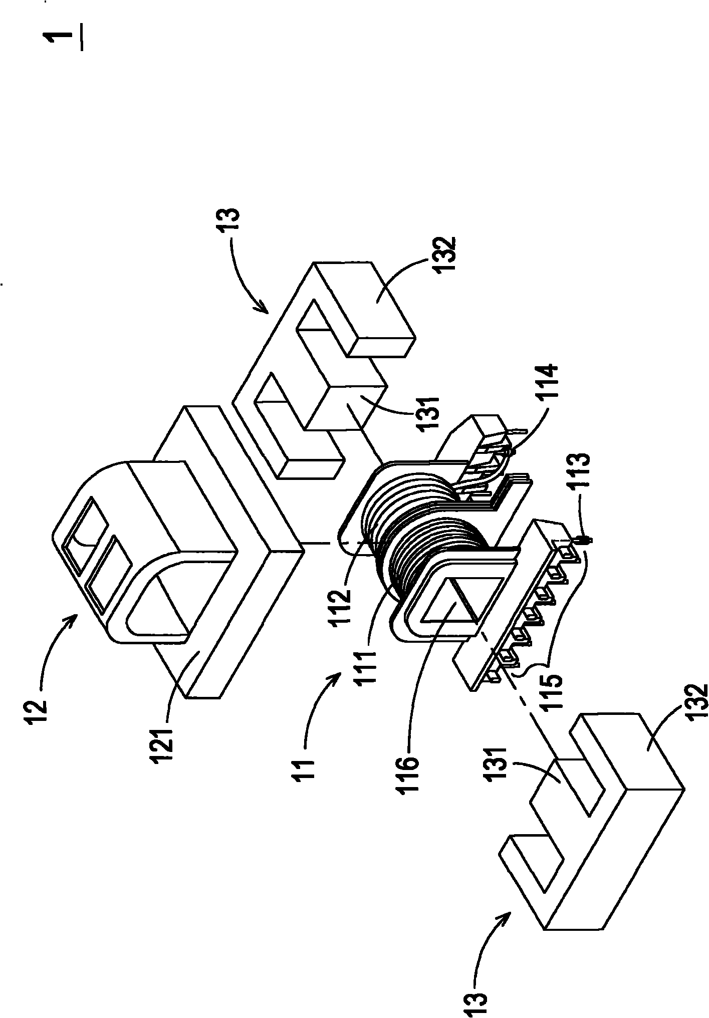
A resonant transformer and winding technology, applied in the direction of transformer, fixed transformer, transformer/inductor magnetic core, etc., can solve the problem that the known transformer 1 is difficult to conform to the development trend of thinning, it is difficult to stably control the leakage inductance value of the transformer 1, and increase the transformer 1. 1 height and other issues, to achieve the effect of reducing the volume, stabilizing the leakage inductance value, and controlling the leakage inductance value
- Summary
- Abstract
- Description
- Claims
- Application Information
AI Technical Summary
Problems solved by technology
Method used
Image

Examples
Embodiment Construction
[0079] Some typical embodiments embodying the features and advantages of the present invention will be described in detail in the description in the following paragraphs. It should be understood that the present invention is capable of various changes in different ways without departing from the scope of the present invention, and that the description and drawings therein are illustrative in nature rather than limiting the present invention.
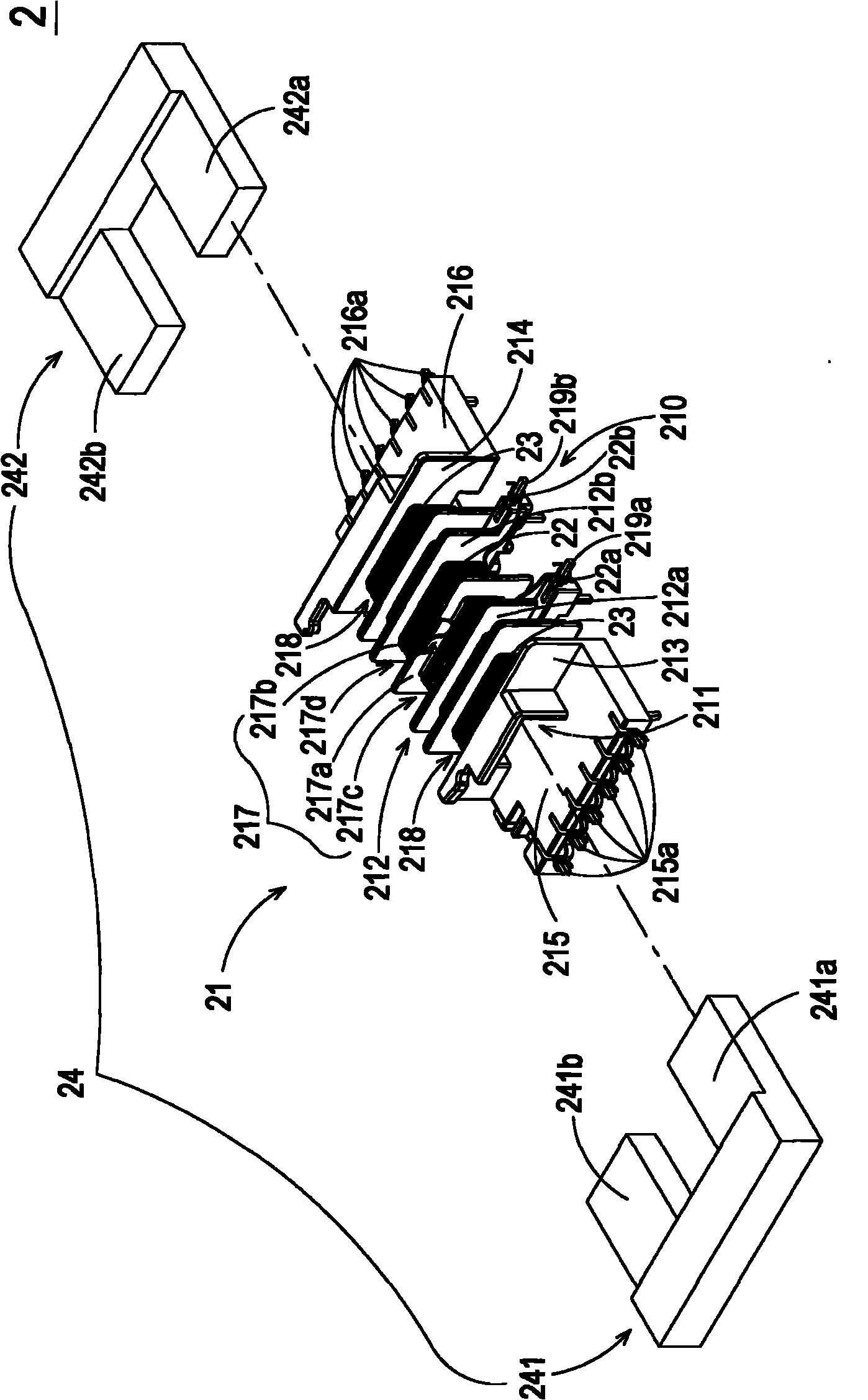
[0080] see figure 2 , which is a schematic exploded view of the structure of the resonant transformer in the first preferred embodiment of the present invention. As shown in the figure, the resonant transformer 2 mainly includes a first winding base 21 , a first primary winding 22 , a plurality of first secondary windings 23 and a magnetic core group 24 .
[0081] The first winding base 21 has a body 210 , a channel 211 , a plurality of partitions 212 , a first side wall 213 , a second side wall 214 , a first connection seat 215 and a ...
PUM
 Abstract
Description
Claims
Application Information