
Small-size rolling type conducting ring assembly applied to space
A rolling type, conductive ring technology, applied in the field of conductive rings, can solve problems such as high machining accuracy, high tolerance requirements, and increased roller wear, and achieve the effects of improving current transmission power, high assembly accuracy, and improving adaptability
- Summary
- Abstract
- Description
- Claims
- Application Information
AI Technical Summary
Problems solved by technology
Method used
Image

Examples
Embodiment Construction
[0018] The present invention will be further described below in conjunction with the accompanying drawings.
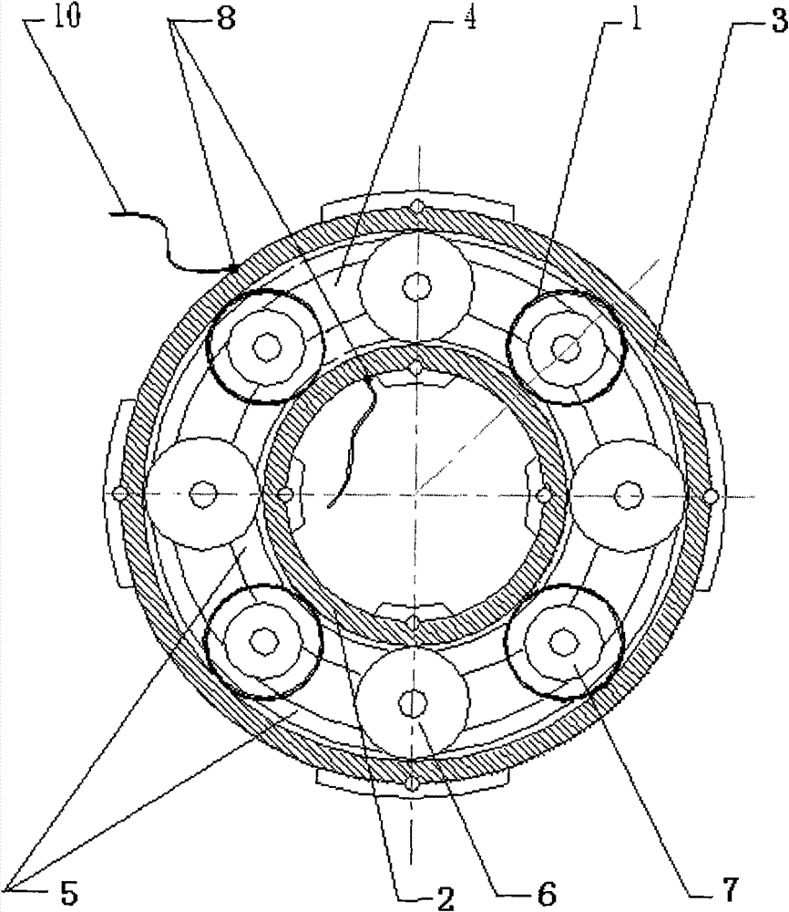
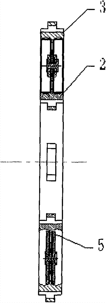
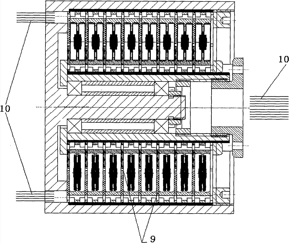
[0019] Such as figure 1 , 2 As shown, it is a small-sized rolling conductive ring assembly for space application according to the present invention, which includes a roller 1 , an inner ring 2 , an outer ring 3 and a cage 4 . The inner ring 2 and the outer ring 3 are concentric. The outer surface of the inner ring 2 and the inner surface of the outer ring 3 are respectively provided with two channels for accommodating the rollers 1 , and bosses 5 are arranged between the channels. The cage 4 is fixed on the bosses 5 of the inner ring 2 and the outer ring 3 through evenly distributed positioning wheels 6 .
[0020] Roller wheels 7 are installed between the positioning wheels 6 . On the upper and lower sides of the cage 4, the roller 1 is set on the roller 7. The roller 1 is circular and the material is beryllium bronze. The roller 1 is stuck in the groove of the i...
PUM
 Abstract
Description
Claims
Application Information