Flow control switch

A flow control and switch technology, applied in the direction of valve lift, valve details, engine components, etc., can solve the problems of high price of solenoid valve, large volume of float valve, low reliability, etc., and achieve low cost, small size and reliable operation Effect

Inactive Publication Date: 2011-09-14
杨彦
View PDF6 Cites 2 Cited by
  • Summary
  • Abstract
  • Description
  • Claims
  • Application Information

AI Technical Summary

Problems solved by technology

This solenoid valve is expensive and has low reliability
The other is composed of a float valve and a one-way valve. This kind of float valve has a large volume and a complex structure.

Method used


Image

  • Flow control switch
  • Flow control switch
  • Flow control switch

Examples


Embodiment 1

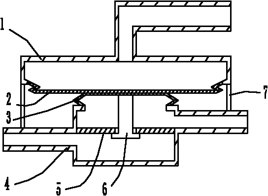
[0027] Such as figure 1 As shown, the flow control switch of this embodiment has a bellows 1 , a valve body 4 and a bracket 7 . The valve seat 5 is located in the valve body 4; the valve body 4 is formed with two interfaces for communicating with the fluid pipeline, the valve seat 5 is fixed in the valve body 4 and is located between the two interfaces in the valve body 4, and the valve The seat 5 is formed with a fluid passage hole. There is an interface on the bellows 1 to connect with the pressure source, as well as the elastic element I2; the valve body 4 has the elastic element II3, the valve seat 5 and the valve core 6, and two interfaces connecting the fluid pipeline; the bracket 7 Connect bellows 1 and valve body 4 together. When the pressure source pressure rises, the elastic element I2 protrudes through the elastic element II3 to push the valve core 6 away from the valve seat, and the valve opens; when the pressure source pressure drops, the elastic element I2 is d...

Embodiment 2

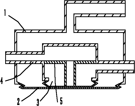
[0029] Such as figure 2 As shown, the flow control switch of this embodiment has a bellows 1 , a valve body 4 and a valve seat 5 . There is an interface on the bellows 1 to connect with the pressure source, and there are elastic elements I2 and elastic elements II3; there are elastic elements II3 and valve seat 5 in the valve body 4, and there are two interfaces connected to the fluid pipeline; the valve body 4 Placed in capsule 1. The fluid valve in this embodiment does not need a valve core, and the valve seat can be directly closed by a diaphragm (elastic element). The fluid passage hole on the valve seat 5 is connected with an extension tube, and the extension tube is pushed against the elastic element II3 and closed or opened by the fluctuation of the elastic element II3 to realize the closing or opening of the fluid valve. When the pressure source pressure rises, the elastic element I2 protrudes and moves up through the elastic element II3 to close the opening of the ...

Embodiment 3

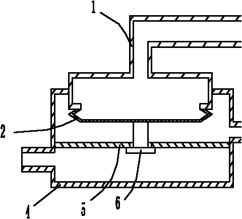
[0031] Such as image 3 As shown, the flow control switch of this embodiment has a bellows 1 and a valve body 4 . The valve seat 5 is located in the valve body 4; the valve body 4 is formed with two interfaces for communicating with the fluid pipeline, the valve seat 5 is fixed in the valve body 4 and is located between the two interfaces in the valve body 4, and the valve The seat 5 is formed with a fluid passage hole. There is an interface on the bellows 1 to connect with the pressure source, and an elastic element I2; the bellows 1 is placed in the valve body 4 . When the pressure source pressure rises, the elastic element I2 protrudes to push the valve core 6 away from the valve seat, and the valve opens; when the pressure source pressure drops, the elastic element I2 sinks to drive the valve core 6 to press the valve seat, and the valve closes.


PUM


Abstract

The invention discloses a flow control switch which comprises a fluid valve. The fluid valve at least comprises a valve body and a valve seat, wherein the valve seat is arranged in the valve body; the valve body is provided with two connectors used for communicating with fluid pipelines, the valve seat is fixed in the valve body and is arranged between the two connectors in the valve body, the valve seat is provided with a fluid through hole. The flow control switch is characterized in that a driving diaphragm capsule with a closed cavity is fixed on the valve body, an elastic element I is arranged on the diaphragm capsule and can drive a diaphragm on the diaphragm capsule to rise and fall according to the change of pressure inside the diaphragm capsule so as to open or close the fluid valve, and the elastic element I and the fluid through-hole on the valve seat are arranged face to face. According to the invention, the driving diaphragm capsule is arranged and can drive the diaphragmto rise and fall because of the pressure change (or pressure change in the diaphragm capsule caused by the temperature change), thus driving a valve plug to press or separate from the valve seat to complete on/off operation. The flow control switch has a simple structure, action reliability, small volume and low cost.

Description

technical field [0001] The invention relates to the field of controlling fluid flow by a diaphragm box or a bellows, in particular to a flow control switch. Background technique [0002] At present, there are two kinds of refrigerator condenser pressure maintaining systems. One is composed of a solenoid valve and a one-way valve. When the compressor is shut down, the two valves are closed together to seal the refrigerant in the condenser until the next time the compressor is turned on. This solenoid valve is expensive and has low reliability. The other is composed of a ball float valve and a one-way valve. This ball float valve has a large volume and a complicated structure. Contents of the invention [0003] The technical problem to be solved by the present invention is to provide a flow control switch with simple structure, high reliability and small volume. [0004] The technical solution adopted by the present invention to solve the above technical problems is: a fl...

Claims


Application Information

Patent Timeline
Patent Type & Authority Applications(China)
IPC IPC(8): F16K1/00F16K31/00
Inventor 杨彦
Owner 杨彦
Why Eureka
Try Eureka