Simple flow control switch

A flow control and switching technology, applied in the direction of diaphragm valves, engine components, diaphragms, etc., can solve the problems of high price of solenoid valves, large volume and low reliability of floating ball valves, and achieve the effects of low cost, small size and reliable action.

Inactive Publication Date: 2013-01-02
杨彦
View PDF8 Cites 1 Cited by
  • Summary
  • Abstract
  • Description
  • Claims
  • Application Information

AI Technical Summary

Problems solved by technology

This solenoid valve is expensive and has low reliability
The other is composed of a float valve and a one-way valve. This kind of float valve has a large volume and a complex structure.

Method used


Image

  • Simple flow control switch
  • Simple flow control switch
  • Simple flow control switch

Examples


Embodiment 1

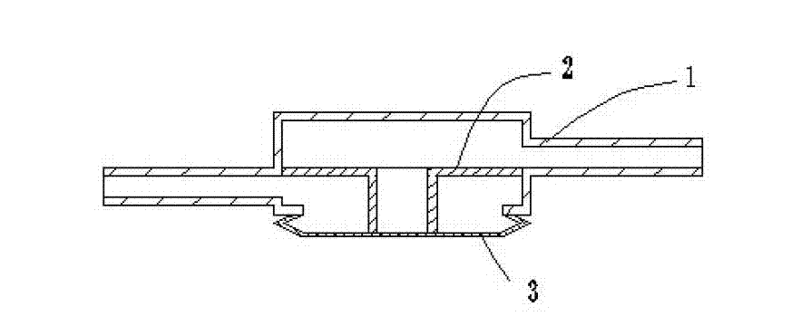
[0018] Such as figure 1 As shown, the flow control switch of this embodiment has a diaphragm 3, a valve body 1 and a valve seat 2, and the valve body also has two interfaces for connecting fluid pipelines. When there is high-pressure fluid in the flow channel, the diaphragm 3 bounces off the valve seat 2, and the valve opens; when the pressure drops, the diaphragm 3 presses the valve seat 2, and the valve closes. The elastic body is a diaphragm, and the diaphragm is directly pressed on the valve seat; when there is high-pressure fluid in the flow channel, the diaphragm bounces off the valve seat, and the valve opens; when there is no pressure in the flow channel, the diaphragm presses the valve seat , to stop the leak.

Embodiment 2

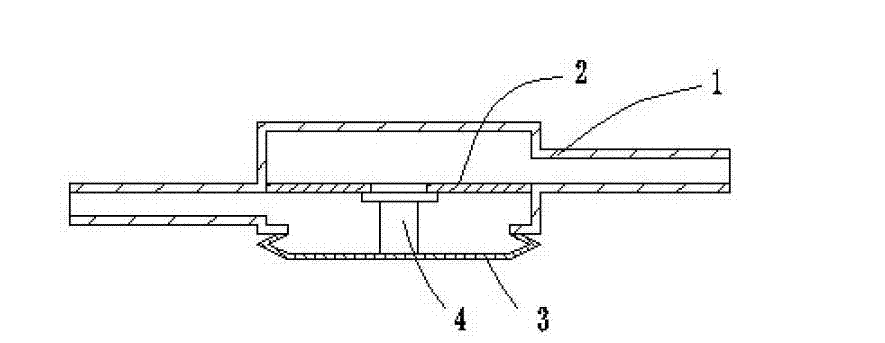
[0020] Such as figure 2 As shown, the flow control switch of this embodiment has a diaphragm 3, a valve body 1, a valve stem 4 and a valve seat 2, and the valve body 1 also has two interfaces for connecting fluid pipelines. When there is high-pressure fluid in the flow channel, the diaphragm 3 bounces up, the valve stem 4 falls away from the valve seat, and the valve opens; when the pressure drops, the diaphragm 3 pushes the valve stem 4 to press the valve seat, and the valve closes. The elastic body is a diaphragm, the diaphragm is pressed on the valve stem, and the valve stem is pressed on the valve seat; when there is high-pressure fluid in the flow channel, the diaphragm bounces up, the valve stem falls, and the valve opens; when there is no pressure in the flow channel , the diaphragm pushes the valve stem to compress the valve seat to prevent leakage.

Embodiment 3

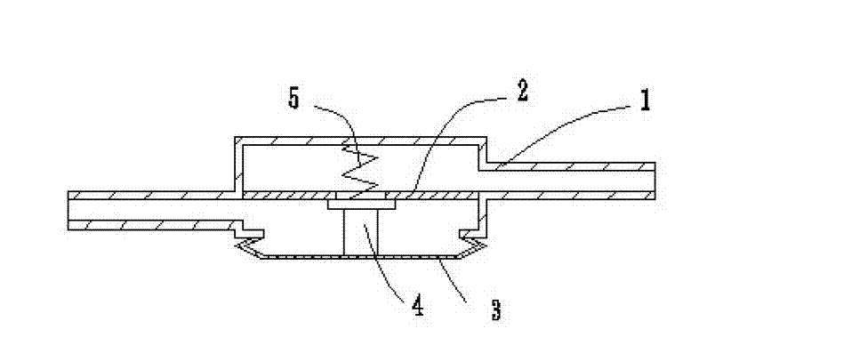
[0022] Such as image 3 As shown, the flow control switch of this embodiment has a diaphragm 3, a valve body 1, a valve stem 4, a spring 5 and a valve seat 2, and the valve body 1 also has two interfaces for connecting fluid pipelines. When there is high-pressure fluid in the flow channel, the diaphragm 3 bounces up, and the valve stem 4 breaks away from the valve seat 2 under the action of the spring 5, and the valve opens; when the pressure drops, the diaphragm 3 pushes the valve stem 4 to press the valve seat, and the valve closes . The elastic body is a diaphragm, the diaphragm is pressed on the valve stem, the valve stem is pressed on the valve seat, and the spring presses the valve stem on the diaphragm when the diaphragm bounces up; when there is high-pressure fluid in the flow channel, the diaphragm When the diaphragm bounces up, the spring presses the valve stem against the diaphragm, and the valve opens; when there is no pressure in the flow channel, the diaphragm p...


PUM


Abstract

The invention discloses a simple flow control switch. The flow control switch consists of a valve body, a valve seat and an elastomer, wherein two joints which are connected with an inlet and an outlet of a fluid are formed in the valve body; the valve seat is fixed in the valve body and is positioned between the two joints of the valve body; and the elastomer is fixed on the valve body and can open or seal the valve seat according to the undulatory motion of pressure change in the valve body. The flow control switch has the elastomer which can be retracted by the change of the pressure in a flow channel, so that the elastomer (or a valve core) and the valve seat are pressed tightly or separated from each other to play a role of opening / closing. The flow control switch has a simple structure, is small in size and low in cost, and acts reliably.

Description

technical field [0001] The invention relates to the field of controlling fluid flow by a diaphragm box or a bellows, in particular to a flow control switch. Background technique [0002] At present, there are two kinds of refrigerator condenser pressure maintaining systems. One is composed of a solenoid valve and a one-way valve. When the compressor is shut down, the two valves are closed together to seal the refrigerant in the condenser until the next time the compressor is turned on. This solenoid valve is expensive and has low reliability. The other is composed of a ball float valve and a one-way valve. This ball float valve has a large volume and a complex structure. Contents of the invention [0003] The technical problem to be solved by the present invention is to provide a simplified flow control switch with simple structure, high reliability and small volume. [0004] The technical solution adopted by the present invention to solve the above-mentioned technical ...

Claims


Application Information

Patent Timeline
Patent Type & Authority Applications(China)
IPC IPC(8): F16K7/17
Inventor 杨彦
Owner 杨彦
Why Eureka
Try Eureka