
Infrared focal plane array and infrared sensor reading circuit

An infrared sensor and readout circuit technology, applied in the field of infrared sensors, can solve the problems of low energy utilization rate and large power consumption

Active Publication Date: 2020-08-04
苏州睿新微系统技术有限公司
View PDF5 Cites 1 Cited by
  • Summary
  • Abstract
  • Description
  • Claims
  • Application Information

AI Technical Summary

Problems solved by technology

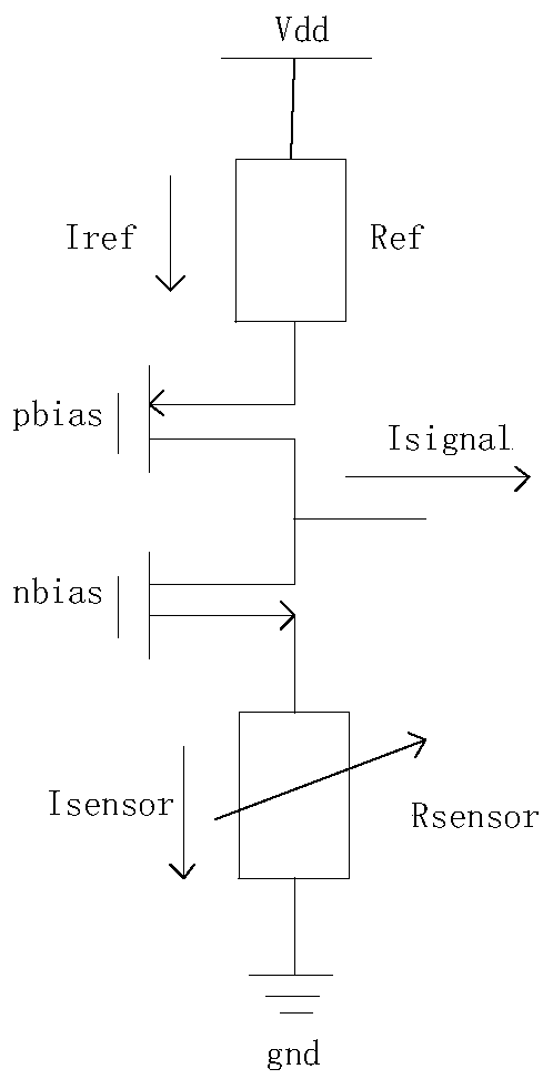
[0003] The circuit diagram of the existing readout circuit is shown in figure 1 As shown, including resistor Ref, two MOS (metal oxide semiconductor, MOS for short) tubes, sensors, and power input from one end of resistor Ref, two MOS tubes are equivalent to current sources in this circuit, two MOS tubes and resistor Ref It will consume a lot of power, resulting in low energy utilization at the sensor, below 50%

Method used


Image

  • Infrared focal plane array and infrared sensor reading circuit
  • Infrared focal plane array and infrared sensor reading circuit
  • Infrared focal plane array and infrared sensor reading circuit

Examples


Embodiment Construction

[0023] In order to enable those skilled in the art to better understand the solution of the present application, the present application will be further described in detail below in conjunction with the drawings and specific implementation methods. Apparently, the described embodiments are only some of the embodiments of this application, not all of them. Based on the embodiments in this application, all other embodiments obtained by persons of ordinary skill in the art without making creative efforts belong to the scope of protection of this application.

[0024] In the following description, a lot of specific details are set forth in order to fully understand the present invention, but the present invention can also be implemented in other ways different from those described here, and those skilled in the art can do it without departing from the meaning of the present invention. By analogy, the present invention is therefore not limited to the specific examples disclosed bel...


PUM


Abstract

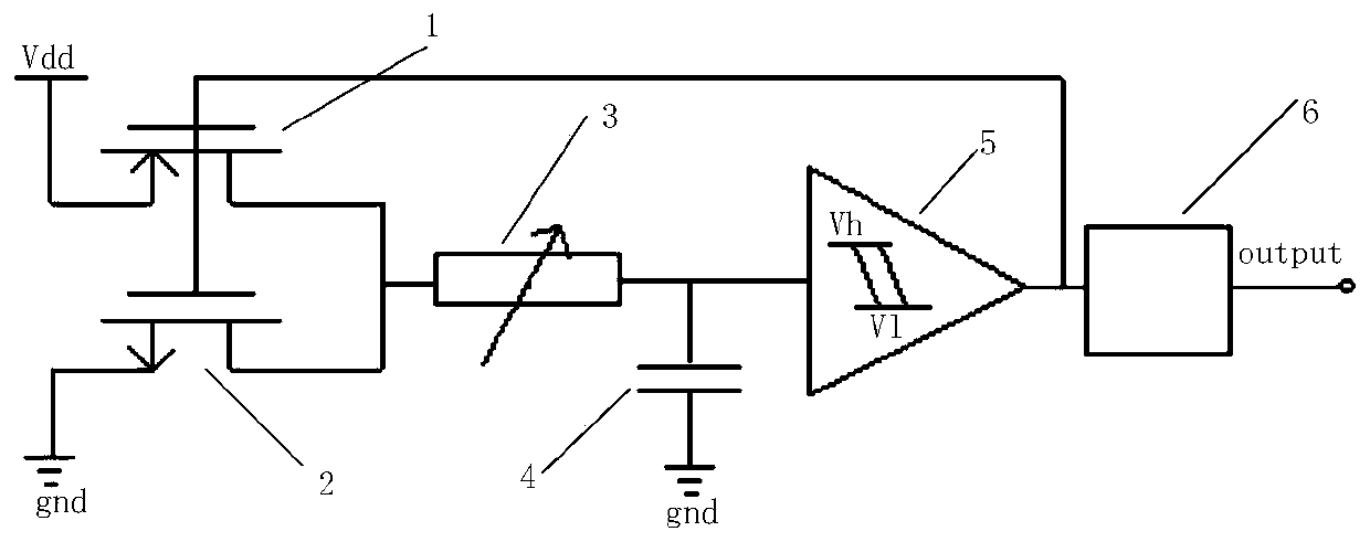
An infrared sensor reading circuit disclosed by the present invention comprises a first transistor, a second transistor, a sensor, an integrating capacitor and a hysteresis comparator. The source of the first transistor is connected with a power supply, the drain of the first transistor is connected with the first end of the sensor, and the grid of the first transistor is connected with the outputend of the hysteresis comparator. The source electrode of the second transistor is grounded, the drain electrode of the second transistor is connected with the first end of the sensor, and the grid electrode of the second transistor is connected with the output end of the hysteresis comparator. The second end of the sensor is respectively connected with the first end of the integrating capacitorand the input end of the hysteresis comparator, the first end of the integrating capacitor is connected with the input end of the hysteresis comparator, and the second end of the integrating capacitoris grounded. The first transistor and the second transistor play a switching role, the resistance is far less than that of the sensor, only the sensor consumes energy, and the energy utilization rateof the sensor is close to 100%, so that the energy utilization rate is improved. The invention further provides the infrared focal plane array with the above advantages.

Description

technical field [0001] The present application relates to the technical field of infrared sensors, in particular to an infrared focal plane array and an infrared sensor readout circuit. Background technique [0002] Infrared imaging technology has important applications in the fields of industry, electric power, medicine, environmental monitoring, security, forest fire prevention and so on. The core component of the infrared imaging system, the infrared focal plane array, includes an uncooled infrared focal plane detector and a readout circuit. The function of the readout circuit is to complete the conversion, amplification and transmission of sensor signals. [0003] The circuit diagram of the existing readout circuit is shown in figure 1 As shown, including resistor Ref, two MOS (metal oxide semiconductor, MOS for short) tubes, sensors, and power input from one end of resistor Ref, two MOS tubes are equivalent to current sources in this circuit, two MOS tubes and resistor...

Claims


Application Information

Patent Timeline
IPC IPC(8): G01J5/24
CPCG01J5/24G01J2005/0077G01J2005/202
Inventor 李聪科谢法彪
Owner 苏州睿新微系统技术有限公司
Learn More