Gearbox with load distribution system

A technology of transmission and synchronizer, which is applied in the direction of gear transmission, belt/chain/gear, mechanical equipment, etc., and can solve problems such as transmission jamming and difficulty in changing

Active Publication Date: 2011-09-14
SMART MFG TECH
View PDF8 Cites 8 Cited by
  • Summary
  • Abstract
  • Description
  • Claims
  • Application Information

AI Technical Summary

Problems solved by technology

However, the nature of the floating relationship between the gears 18, 19 on the main shaft makes this modification difficult because the synchronizers require tight tolerances to engage correctly
Therefore, the use of synchronizers has the risk of causing the transmission to jam due to the aforementioned problems related to the mechanical tolerances between the gears

Method used


Image

  • Gearbox with load distribution system
  • Gearbox with load distribution system
  • Gearbox with load distribution system

Examples


Embodiment Construction

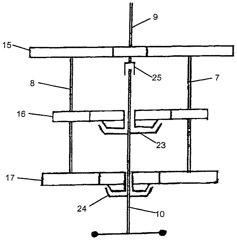
[0029] figure 1 The transmission shown in has been discussed in the context of the present invention.

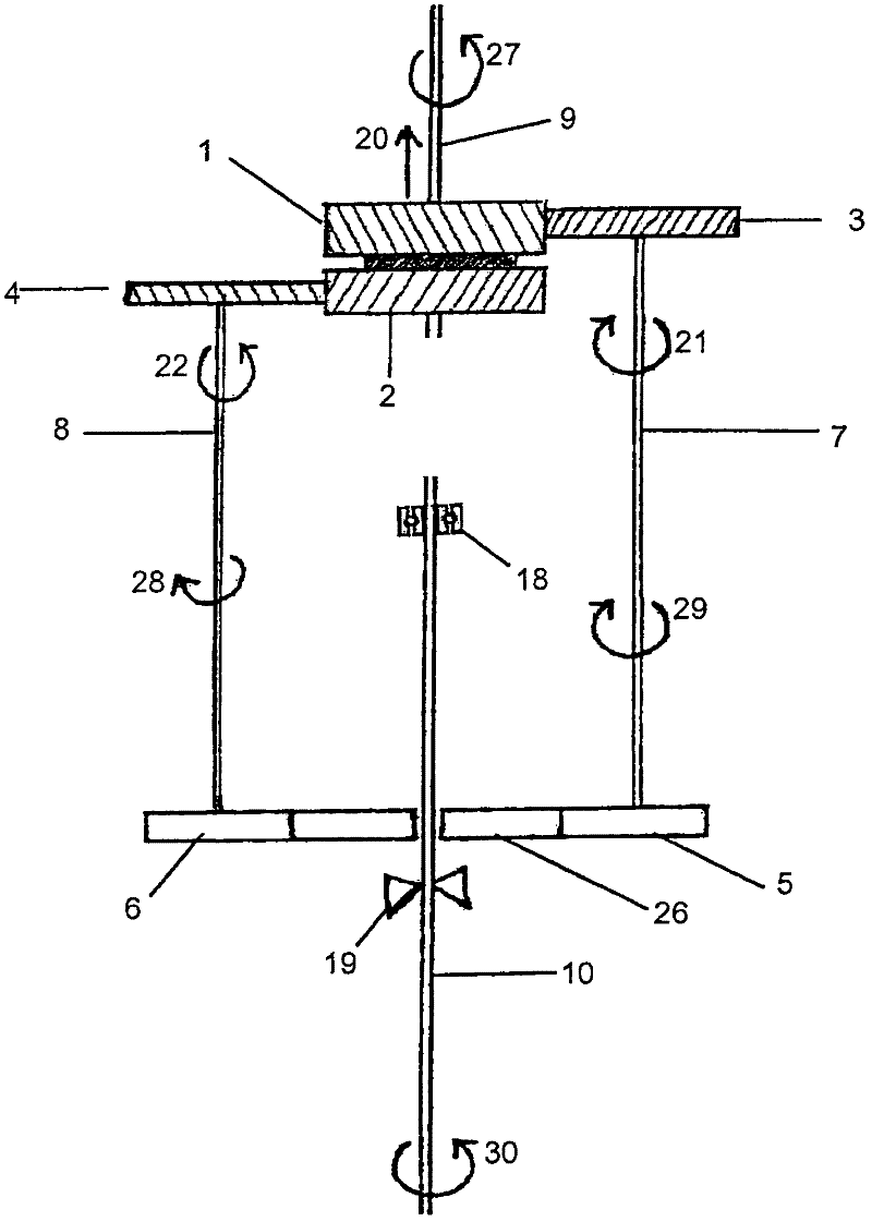
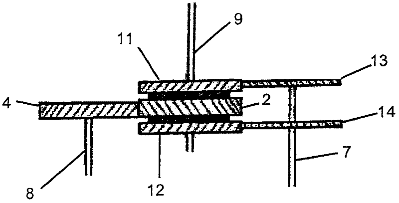
[0030] figure 2 The transmission shown in includes two helical gears 1, 2 in opposite directions, which are mounted on an input shaft 9 to be rotated by an input power source. These input gears 1, 2 are free to move axially, but whether axially or rotationally, the input gears 1, 2 are constrained to move in concert. Pairs of gears may be constrained by, for example, manufacturing them as one piece, or by connecting the two gears together with bolts, screws, welding or other connecting means. The set distance between the two input gears 1, 2 can be zero or greater than zero. Where this distance is non-zero, the gap between the gears may be maintained by rigid or compressible material inserted between the gears, for example mounted to the input shaft 9 .

[0031] The meshing of helical gears tends to induce opposing axial forces which will be approximately proportional t...


PUM


Abstract

A gearbox comprising: an input shaft (9) having first and second helical input gears (1, 2) of opposite hand fixed axially relative to each other and axially moveable in tandem; an output shaft (10); first and second lay shafts (7, 8) offset from the axis of the input shaft (9, 10) and configured to engage with the input and output shafts (9, 10) for transmitting rotational movement from the input shaft (9) to the output shaft (10), each lay shaft (7, 8) comprising an input gear (3, 4) such that the first lay shaft (7) engages with the first input gear (1) but not the second input gear (2) and the second lay shaft (8) engages with the second input gear (2) but not the first input gear (1 ),- and two or more output gears (26) rotatably mounted on, and selectively engageable with, the output shaft (10), the output gears being in continuous mesh with corresponding output gears (5, 6); on the first and second lay shafts (7, 8), wherein the gearbox is configured such that an imbalance in load sharing between the input shaft (9) and the first and second lay shafts (7, 8) when the output shaft (10) is engaged with the first and second lay shafts (7,8) results in axial movement of the first and second input gears (1, 2) tending to reduce the imbalance.

Description

technical field [0001] This invention relates to transmissions used to convert the torque and speed of a source of rotational power, such as an engine or other electric machine. Background technique [0002] Transmissions are commonly used in motor vehicles to allow the engine to operate within its operating limits while taking into account changes in vehicle speed. Gear pairs in transmissions are typically designed with backlash due to mechanical tolerances between the gears and thermal expansion of the gear teeth. Without a small amount of backlash, there is a risk of the transmission jamming under certain conditions. [0003] figure 1 The structure of a particular type of known variator, such as that described in document US 4,754,665, is shown exemplarily in . This type of transmission takes input rotational power from an input shaft 9 and transmits the input rotational power to a pair of countershafts 7 and 8 (also referred to as countershafts) through a head gear se...

Claims


Application Information

Patent Timeline
Patent Type & Authority Applications(China)
IPC IPC(8): F16H1/22F16H3/095
CPCF16H3/095F16H1/22Y10T74/19233
Inventor 周长秀
Owner SMART MFG TECH
Why Eureka
Try Eureka