self inflatable boat

An automatic inflatable, hull technology, applied in the direction of foldable/inflatable hulls, ships, ship salvage, etc., can solve the problem of time-consuming and labor, and achieve the effect of ensuring safety

Inactive Publication Date: 2015-07-29
따리엔조양워터크래프트컴퍼니리미티드
View PDF6 Cites 1 Cited by
  • Summary
  • Abstract
  • Description
  • Claims
  • Application Information

AI Technical Summary

Problems solved by technology

[0006] However, the above-mentioned self-inflation system for an inflatable boat technology still needs to inject air through many hoses, and still needs to consume a lot of time and labor.

Method used


Image

  • self inflatable boat
  • self inflatable boat
  • self inflatable boat

Examples


Embodiment Construction

[0055] The present invention will be described in detail below in conjunction with the accompanying drawings and embodiments.

[0056] For the implementation of the present invention, it is described in detail with reference to drawings as follows:

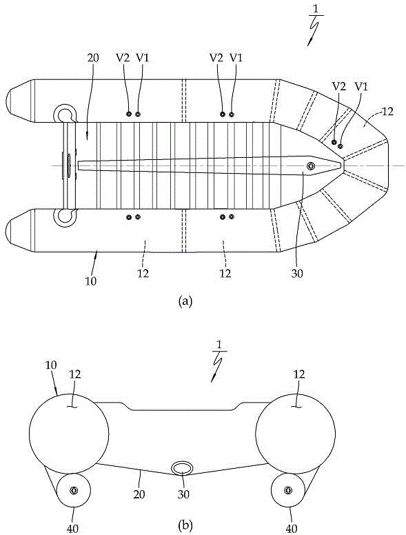
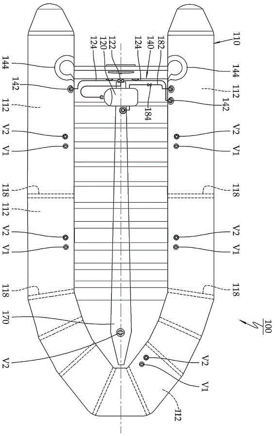
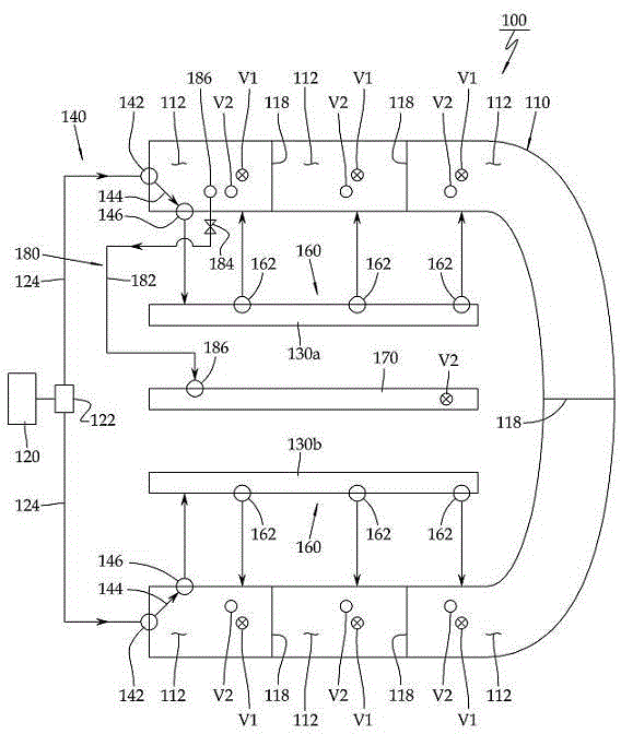
[0057] The automatic inflatable boat 100 of the present invention is as figure 2 As shown, the original installation status of the original intake valve V1 on each air chamber 112 in the hull part 110 remains unchanged, and an overpressure safety valve I162 and an overpressure safety valve V2 are added to each air chamber 112. When each air chamber 112 When the air pressure inside exceeds the specified pressure, the excess air can be automatically discharged outside.

[0058] The air chambers 112 of the self-inflating boat 100 of the present invention are separated within the hull portion 110 by partitions 118 .

[0059] The self-inflatable boat 100 of the present invention generates compressed air from a compressed air supply ...


PUM


Abstract

The invention discloses an automatic inflatable boat. It includes: a tubular hull part with a plurality of air chambers inside; a velocity tube or an air delivery pipe installed on the tubular hull part; a compressed air supply source is fixed behind the tubular hull part, thereby The compressed air supply part that generates compressed air and provides compressed air to the velocity tube; the air distribution part that supplies compressed air to each air chamber of the hull part at the design pressure through the above velocity tube; the above hull part supplies the keel with the design pressure Air connection section for air. In the present invention, through the high-pressure intake valves at 1-2 places, the air of the required pressure is quickly input to each air chamber at the same time, so it can be quickly put into use in an emergency. It is especially suitable for the evacuation and transfer of rescue ships or military ships with emergency needs, ensuring that any air chamber in the hull part is damaged without affecting the remaining air chambers, ensuring safety.

Description

technical field [0001] The present invention relates to an inflatable boat with automatic inflation function. Through the compressed air source installed on the hull and the high-pressure air delivery pipe assembly, the boat quickly fills the multiple air chambers in the hull with design pressure, shortens the inflation time, and enables the inflatable boat to operate in an emergency. Quickly put into use. Background technique [0002] General inflatable boat 1, such as figure 1 a and figure 1 As shown in b, it is composed of a hull portion 10, a bottom plate 20, a keel 30, a velocity tube 40, etc., which are formed by each air chamber 12. Each of these air chambers is filled with air, placed in water, and driven by a motor or paddles. [0003] This method of inflating each air chamber 12 one by one requires an air intake valve V1 and an overpressure safety stop valve V2 to be provided in each air chamber 12 . Since it is necessary to inflate each air chamber 12 separat...

Claims


Application Information

Patent Timeline
Patent Type & Authority Patents(China)
IPC IPC(8): B63B7/08
Inventor 赵承男
Owner 따리엔조양워터크래프트컴퍼니리미티드
Why Eureka
Try Eureka