Free wheel, especially for a crank cvt

A transmission, free technology, applied in the direction of clutch, one-way clutch, mechanical equipment, etc., can solve problems such as hindering the clamping function, and achieve the effect of improving the buffer function

Inactive Publication Date: 2012-04-25
SCHAEFFLER TECH AG & CO KG
View PDF6 Cites 0 Cited by
  • Summary
  • Abstract
  • Description
  • Claims
  • Application Information

AI Technical Summary

Problems solved by technology

[0007] A disadvantage is that these clamping bodies can undesirably twist about their own axis of rotation, especially in the case of cageless freewheels, in highly dynamic situations, thereby impairing the clamping function.

Method used


Image

  • Free wheel, especially for a crank cvt
  • Free wheel, especially for a crank cvt
  • Free wheel, especially for a crank cvt

Examples


Embodiment Construction

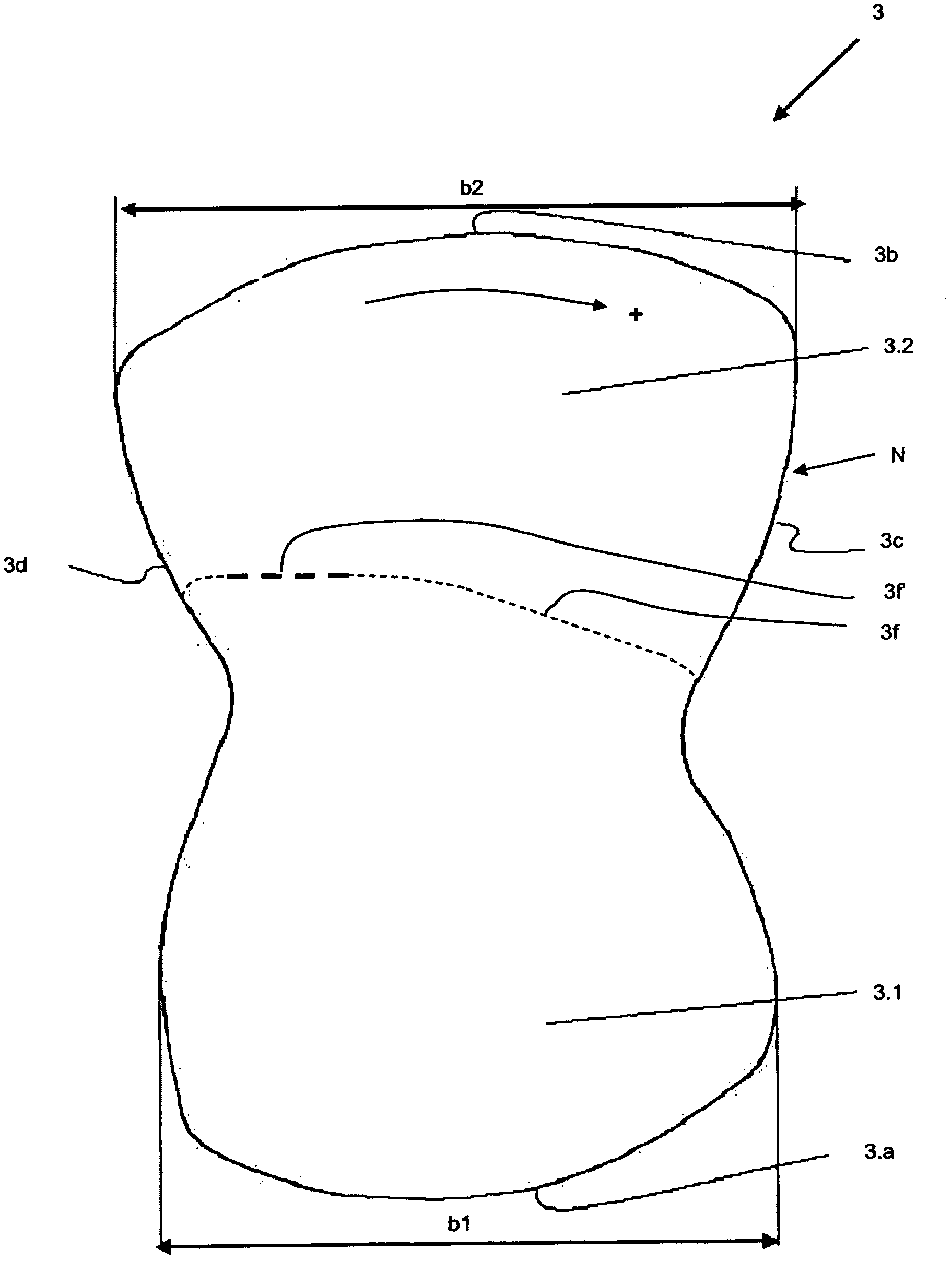
[0023] figure 1 Shows a front view of the clamping body 3 with a base region 3.1 and a head region 3.2, wherein the base region 3.1 has a contact surface 3a in the direction of the inner ring, not shown here, and the head region 3.2 faces the freewheel In the direction of the outer ring, not shown here, there is a contact surface 3b.

[0024] The base region 3 . 1 has a width b1 , the head region has a larger width b2 than this. A constriction, not shown in detail, is formed between them.

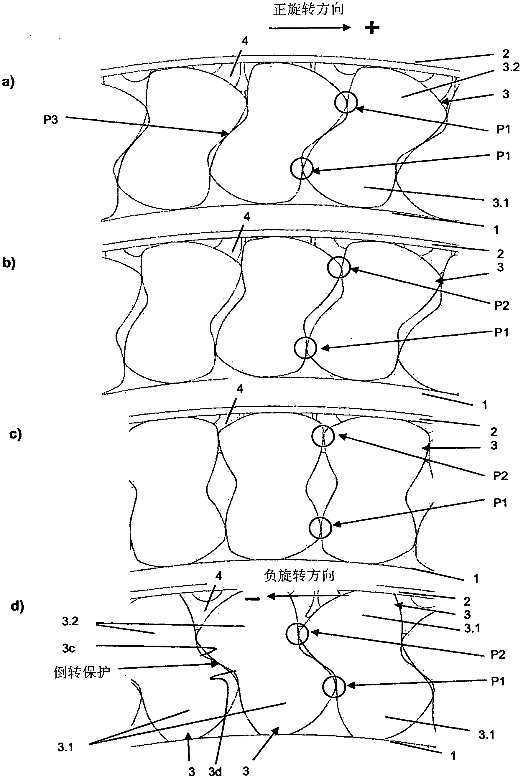
[0025] In the pivoting direction of the clamping body 3 indicated by the arrow, a first abutment surface 3c and, conversely, a second abutment surface 3d are formed during shock loading (positive direction of rotation+), which point to the not shown Out of the adjacent clamping body.

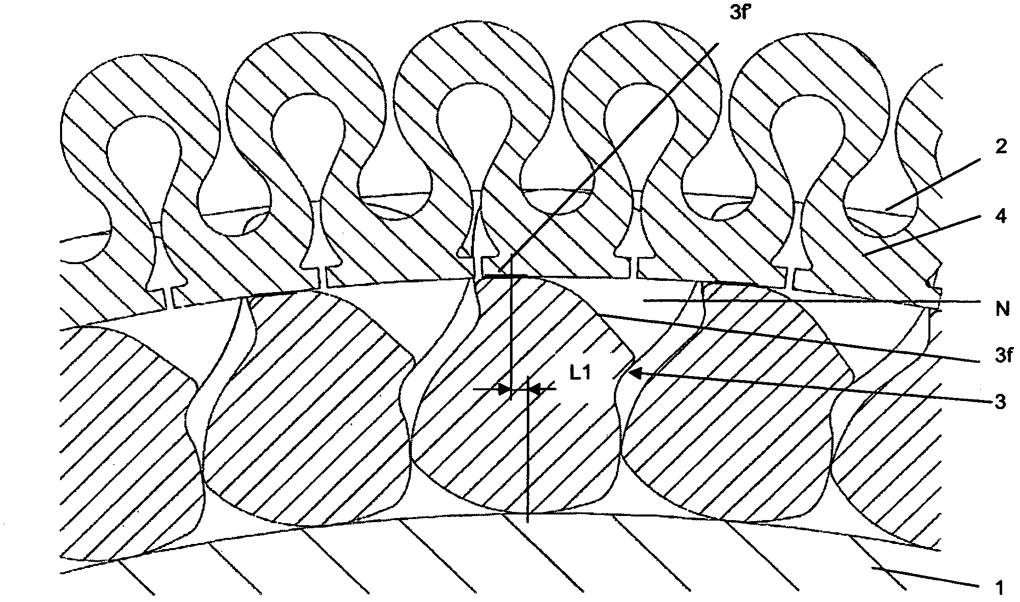
[0026] The clamping body 3 also has a buffer groove N open towards the outer ring (see image 3 and 4 ), which has a pressure surface 3f indicated here by a dotted line, on which a spring not shown, for ...


PUM


Abstract

The invention relates to a free wheel, especially for a crank CVT, comprising an inner ring (1), an outer ring (2) that can rotate in at least one rotary direction in relation to the inner ring (1) and is arranged radially around the inner ring (1), and a plurality of clamping bodies comprising a head region and a foot region, that are applied to each other between the inner ring and the outer ring and can be subjected to the radially inwardly acting elastic force of a peripheral spring (4) engaging in a spring groove, towards the inner ring. According to the invention, the guidance of the clamping bodies is carried out at the same time in the head region and in the foot region, and the clamping bodies are in the form of a cycloid in the head region (3b) and the foot region (3a).

Description

technical field [0001] The present invention relates to freewheels, especially for crankshaft CVT transmissions. Background technique [0002] A CVT is a monotonically switching transmission, in which the rotational speed relationship of the drive shaft and the driven shaft, ie the transmission ratio, can assume endlessly multiple values ​​(stages) within a defined range. This can also include a stationary state of an axis or a reversal of the direction of rotation. The movement is transmitted by means of a non-fixed coupling of components, the geometry of which determines the transmission action according to the principle of leverage. A change in the transmission ratio is effected by changing the geometry of these components, which can be carried out simultaneously without changing the geometry at the coupling points of the components. [0003] For this purpose, many freewheel arrangements for crankshaft CVT transmissions have clamping bodies which are arranged between an...

Claims


Application Information

Patent Timeline
Patent Type & Authority Applications(China)
IPC IPC(8): F16D41/07
CPCF16D41/07
Inventor L·梅恩
Owner SCHAEFFLER TECH AG & CO KG
Why Eureka
Try Eureka