Measuring apparatus with two spliced shafts for large-caliber convex aspheric surface
A measuring device and aspheric technology, applied in the field of optical detection, can solve the problems of many degrees of freedom of movement, complex movement mechanism, insufficient detection ability, etc., and achieve the effect of less freedom of movement, simple device structure, and high precision.
Active Publication Date: 2010-12-01
HARBIN INST OF TECH
View PDF4 Cites 0 Cited by
- Summary
- Abstract
- Description
- Claims
- Application Information
AI Technical Summary
Problems solved by technology
Chinese Patent Publication No. CN101241000, published on August 13, 2008, the title of the invention is "Aberration-free Point Method Aperture Splicing Measurement Method for High Steep Convex Quadratic Aspheric Surface" which discloses a high steep convex quadratic aspheric surface. The aberration-free point method sub-aperture stitching measurement method combines the aberration-free method with the sub-aperture stitching method to expand the detection aperture of the aspheric surface, but the detection object of this method is still limited to the quadric reflective surface, and this method requires For large-diameter auxiliary mirrors, especially for testing convex aspheric surfaces, the diameter of the auxiliary mirror is often several times that of the mirror to be tested
This method is only suitable for flat, spherical and moderately aspheric optical parts with an aperture of less than 200mm, and cannot be used for the detection of large-diameter aspheric surfaces, especially large-diameter convex surfaces, and the system requires a high-precision workbench with 6 degrees of freedom, free movement Many degrees, high precision requirements for movement and positioning, and difficult control
Chinese Patent Publication No. CN101251435A, published on August 27, 2008, the title of the invention is "Large Optical Mirror Surface Sub-aperture Stitching Workstation", which discloses a five-dimensional motion adjustment based on the interferometer and a two-dimensional tilt adjustment of the measured mirror. Horizontal optical mirror sub-aperture splicing workstation, but the motion mechanism of this scheme is complicated, there are many degrees of freedom of motion, the measurement chain is too long, more error sources are introduced, and the precision control is difficult, and it is aimed at large-diameter aspheric surfaces, especially large-diameter Insufficient detection capability for convex aspheric surfaces
Method used
View moreImage
Smart ImageViewing Examples
Examples
Embodiment Construction
Login to View More PUM
 Abstract
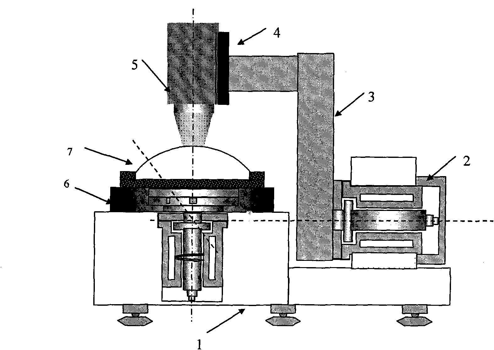
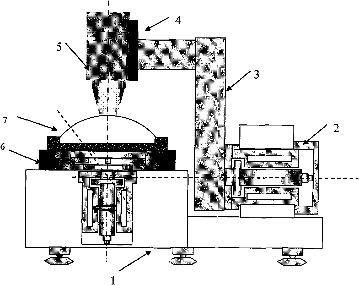
The invention relates to a measuring apparatus with two spliced shafts for a large-caliber convex aspheric surface, belonging to the optical detection field. The measuring apparatus comprises a vibration-isolation base, an optical wave surface interferometer, a vertical ultra-precise air-floating revolving platform and a horizontal ultra-precise revolving haft, wherein the vertical ultra-precise air-floating revolving platform and the horizontal ultra-precise revolving shaft are both installed on the vibration-isolation base; a Z-shaped cantilever beam is fixed on the horizontal ultra-preciserevolving shaft; a linear guide rail is fixed on the tail end of the Z-shaped cantilever beam; the linear guide rail is provided with the optical wave surface interferometer; a revolving axis of the vertical ultra-precise air-floating revolving platform is orthogonal with that of the horizontal ultra-precise revolving shaft, and an optical axis of the optical wave surface interferometer passes through the orthogonal point; the optical axis of an aspheric surface to be measured is superposed with the revolving axis of the vertical ultra-precise air-floating platform; and three crossing points of an aspheric surface pericenter, a measuring wave front focus of the optical wave surface interferometer and the crossing points of the revolving axis of the horizontal ultra-precise revolving shaftand the revolving axis of the vertical ultra-precise air-floating platform are superposed or have very small three-dimensional concentricity. In the technical scheme, the mechanism is simple, the measurement chain is short, and the high-precision detection of the large-caliber convex aspheric surface can be realized by the precision advantage of the revolving motion.
Description
Large-diameter convex aspheric two-axis splicing measuring device technical field The invention belongs to the technical field of optical detection, and mainly relates to a large-diameter convex aspheric surface two-axis splicing measuring device. Background technique Aspherical optical components have the advantages of improving the imaging quality of the system, correcting aberrations, increasing the relative aperture of the system, and expanding the field of view. Light energy is lost, so it has been more and more widely used in modern optical systems. Especially in the fields of space cameras, astronomical telescopes, ground-based space target detection and recognition, laser weapon systems, and inertial confinement fusion, aspheric devices have become key components that determine system performance. High-precision detection of aspheric surface shape quality is one of the most critical technologies for the wide application of aspheric surfaces, and it is also the ba...
Claims
Login to View More Application Information
Patent Timeline
 Patent Type & Authority Patents(China)
IPC IPC(8): G01B11/24G01B9/02G01M11/02
Inventor 谭久彬王伟波刘俭
Owner HARBIN INST OF TECH
Features
- R&D
- Intellectual Property
- Life Sciences
- Materials
- Tech Scout
- Unparalleled Data Quality
- Higher Quality Content
- 60% Fewer Hallucinations
Learn More Browse by: Latest US Patents, China's latest patents, Technical Efficacy Thesaurus, Application Domain, Technology Topic, Popular Technical Reports.
© 2025 PatSnap. All rights reserved.Legal|Privacy policy|Modern Slavery Act Transparency Statement|Sitemap|About US| Contact US: help@patsnap.com


