Realization method of optocoupler drive-based broad impulse grid control modulator

A technology of optocoupler drive and realization method, which is applied in the direction of pulse generation, pulse technology, electric pulse generation, etc., and can solve the problem that the width modulation pulse cannot be satisfied.

Inactive Publication Date: 2012-05-23
THE 724TH RES INST OF CHINA SHIPBUILDING IND
View PDF3 Cites 6 Cited by
  • Summary
  • Abstract
  • Description
  • Claims
  • Application Information

AI Technical Summary

Problems solved by technology

The isolated drive method using pulse transformers can no longer meet the requirements of a wide modulation pulse of several hundred microseconds

Method used


Image

  • Realization method of optocoupler drive-based broad impulse grid control modulator
  • Realization method of optocoupler drive-based broad impulse grid control modulator
  • Realization method of optocoupler drive-based broad impulse grid control modulator

Examples


Embodiment Construction

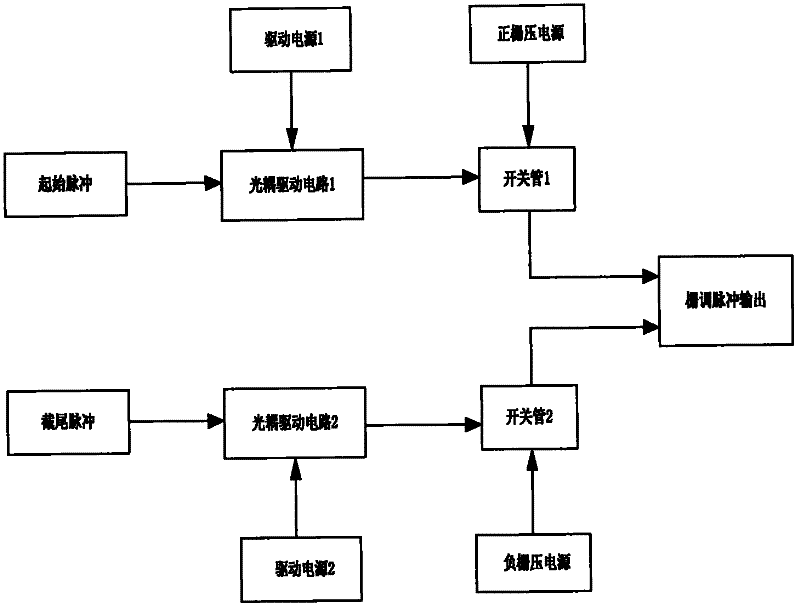
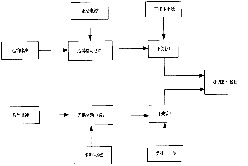
[0011] The principle block diagram of wide pulse gate control modulator based on optocoupler drive is as follows: figure 1 As shown, the gate-controlled modulator is composed of a driving signal generating circuit, an optocoupler driving circuit, a driving power supply, a positive and negative bias power supply, and a switch tube. The initial pulse signal passes through the optocoupler isolation drive circuit to form an initial drive signal, which triggers the switch tube 1 to be turned on, and adds a positive bias power supply to the grid, so that the traveling wave tube outputs radio frequency power. The truncated pulse signal forms a truncated driving signal after passing through the optocoupler isolation driving circuit, which triggers the conduction of the switch tube 2, applies the negative bias power to the grid, and turns off the RF power output of the traveling wave tube.

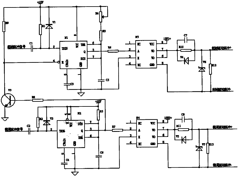
[0012] Driving signal generation and driving circuit schematic diagram figure 2 shown. In th...


PUM


Abstract

The invention relates to a realization method of an optocoupler drive-based broad impulse grid-control traveling-wave tube modulator, wherein the functional block diagram of the method is shown as the figures. An isolation driving circuit of a grid-control traveling-wave tube modulator switching tube is realized by a high-speed optocoupler, so that the broad impulse output requirement of the grid-control traveling-wave tube modulator is met. In the realization method, the width of the grid electrode modulation impulse is only determined by time difference between an external initial impulse signal and a chopped impulse signal and is not related to a modulator circuit. The requirement of the grid electrode width modulation impulse can be met only if the adjusting time of the time difference is long enough. At the same time, the limit of maximum modulation impulse can be realized due to the design of the circuit in the modulator, so that the traveling-wave tube can be protected.

Description

technical field [0001] The invention belongs to the radar transmitter gate control modulator technology, and is a realization method of a wide pulse gate control modulator based on optocoupler drive. Background technique [0002] The main function of the pulse modulator is to control the on-off of the electron beam of the microwave tube, control or stimulate the work of the microwave tube, thereby generating various pulsed microwave sources required. The pulse modulator plays an extremely important role in the radar transmitter and is an important part of the radar transmitter. Its comprehensive index performance has an important impact on the transmitter. [0003] Grid modulation is a commonly used modulation method in traveling wave tubes. Its basic working method is to control the turn-on timing of different switching tubes, so that the positive bias power and negative bias power are applied to the grid of the traveling wave tube in turn, so as to control the pulse power...

Claims


Application Information

Patent Timeline
Patent Type & Authority Applications(China)
IPC IPC(8): H03K3/017H03K17/08H03K17/78
Inventor 杨钰辉
Owner THE 724TH RES INST OF CHINA SHIPBUILDING IND
Why Eureka
Try Eureka