Rail destruction detection method based on magnetostriction and longitudinal ultrasonic guided wave

A technology of ultrasonic guided wave and magnetostriction, which is applied in the direction of using sound wave/ultrasonic wave/infrasonic wave to analyze solids, etc. It can solve problems such as shallow detection depth, difficult coupling, and radiation hazards to the human body.

CN102520068BActive Publication Date: 2013-12-18JINAN UNIVERSITY
3 Cites 0 Cited by

Patent Information

Authority / Receiving Office
CN · China
Patent Type
Patents(China)
Current Assignee / Owner
Publication Date
2013-12-18

Smart Images

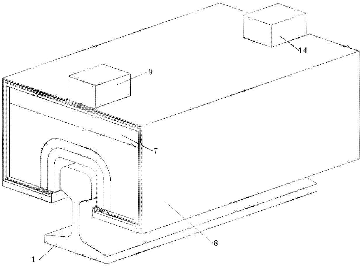
  • Figure 1
    Figure 1
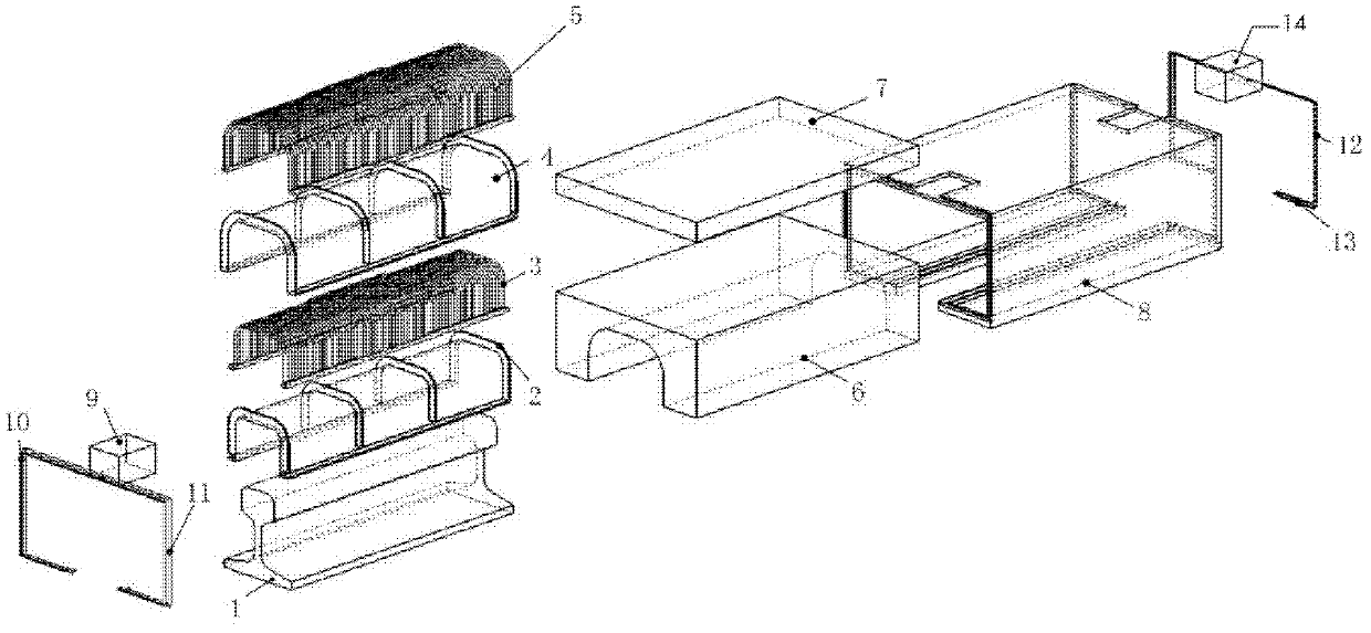
  • Figure 2
    Figure 2
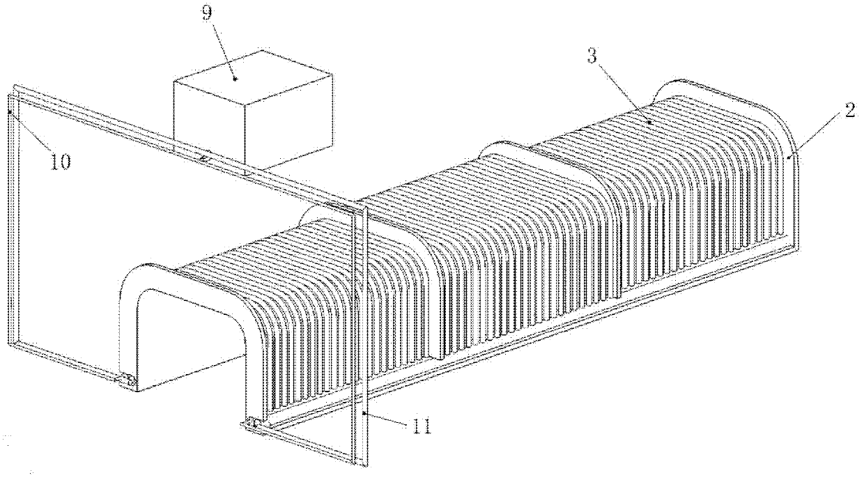
  • Figure 3
    Figure 3
Patent Text Reader

Abstract

The invention discloses a rail damage detection device and method based on magnetostriction and longitudinal ultrasonic guided wave, which are applied in the field of railway traffic nondestructive detection. The rail damage detection device comprises a shell, wherein an inner wire support, an inner coil, an outer wire support, an outer coil, a yoke and a permanent magnet are arranged in the shell; a current input port, an inner coil current input electric wire and an inner coil current output electric wire are arranged at one end of the shell; an outer coil current output electric wire, an outer coil current loop electric wire and a voltage output port are arranged at the other end of the shell; and the upper part of the shell is fixedly connected with a rail detection vehicle. The rail damage detection method comprises the following steps of: exciting induced electromotive force by utilizing magnetostriction and longitudinal ultrasonic guided wave, and indirectly measuring time and strength generated by a defect reflective waveguide signal according to the induced electromotive force, and further determining the destruction position and the destruction size. The rail damage detection device and method can be used for carrying out accurate detection on trace destruction inside and outside the rail, and have the advantages of long detection distance and high detection efficiency.
Need to check novelty before this filing date? Find Prior Art

Description

technical field

[0001] The invention relates to the field of rail transit non-destructive testing, in particular to a rail damage testing method based on magnetostrictive technology and longitudinal ultrasonic guided wave technology. Background technique

[0002] At present, in the field of non-destructive testing of rail transit, most of the detection methods such as magnetic flux leakage method, infiltration method and eddy current method are used to detect the damage of rails. At the same time, people are still using ray method and ultrasonic method to monitor the degree of track damage. Now widely used is the track inspection car technology. The detection system mainly integrates ultrasonic and electromagnetic induction detection technologies and optical sensors on the platform of the rear-mounted track detection vehicle. In addition, Imperial College London developed a piezoelectric sensor-based longitudinal ultrasonic guided wave rail damage detection equipment. The...

Examples

Embodiment 1

[0056] A rail damage detection device based on magnetostriction and longitudinal ultrasonic guided waves has the advantages of long detection distance, short detection time, real-time detection during online operation of a non-contact rail inspection vehicle, and early crack damage of the rail can be found. Its mechanical parts such as figure 1shown. Its appearance is a cuboid with an open lower end, the shape of the lower end opening is similar to the shape of the rail head, slightly larger than the rail to ensure its non-contact with the rail; the upper part is connected with the rail inspection vehicle. It includes inner layer wire holder 2, inner layer coil 3, outer layer wire holder 4, outer layer coil 5, yoke iron 6, permanent magnet 7, shell 8, current input port 9, electrical inner layer coil current input wire 10, inner Layer coil current output wire 11, outer coil current output wire 12, outer coil current loop wire 13, voltage output port 14, specifically as fig...