Rail destruction detection device and method based on magnetostriction and longitudinal ultrasonic guided wave

An ultrasonic guided wave and magnetostrictive technology, which is applied in the direction of analyzing solids using sound waves/ultrasonic waves/infrasonic waves, can solve the problem of radiation hazards to the human body, cannot meet the needs of large-scale rail damage detection, and equipment cannot move on rails, etc. question

Active Publication Date: 2012-06-27
JINAN UNIVERSITY
View PDF3 Cites 32 Cited by
  • Summary
  • Abstract
  • Description
  • Claims
  • Application Information

AI Technical Summary

Problems solved by technology

This greatly limits the efficiency of this method in practical use
[0005] (2) Penetration method, which is highly sensitive to the detection of surface opening cracks, but it is not ideal for workpieces with coatings and wet surfaces, and the judgment of defects depends on the experience of inspectors, which cannot meet the needs of large-scale rails The need for damage detection
However, the eddy current testing method and the above two methods can only detect the surface or near-surface defects of metal conductors, and the detection depth is very shallow, so it is impossible to know the damage inside the rail
[0007] (4) The ray method is very effective for the detection of defects under the surface of the workpiece, but the ray radiation is harmful to the human body, and safety protection must be carried out during the detection, and some working conditions are not easy to implement
[0008] (5) The ultrasonic testing method is very effective for detecting defects under the surface of the workpiece, but the coupling agent is required for detection, and the efficiency is low, and the determination of defects also depends on the experience of technicians
But on the other hand, when calculating and processing these data through mathematical principles, these mathematical methods are not good at dealing with unusual features that appear in the track, such as track intersections, etc.
[0009] (6) The piezoelectric sensor-based longitudinal ultrasonic guided wave rail damage detection equipment designed by Imperial College of Technology in the United Kingdom Because the piezoelectric sensor needs to be in close contact with the rail, it needs to be coated with a couplant on the surface of the rail to be detected, which makes the The rail where the sensor is clamped must be kept clean and flat without rust, otherwise it will be difficult to achieve coupling
But the biggest problem with this equipment is that the piezoelectric sensor is a contact-type guided wave excitation and receiving device. Therefore, each detection takes at least 20 minutes and the equipment cannot be moved on the rail during detection, so online damage detection cannot be realized
This greatly restricts the detection efficiency for thousands of kilometers of railway tracks
[0010] (7) Although the equipment developed by the University of California, San Diego uses non-contact laser technology to excite ultrasonic guided waves, the ultrasonic guided waves excited by this technology are in bending mode
The laser signal amplifier is unstable and the detection signal noise is too large
Therefore, the rail inspection vehicle carried by the inspection equipment can only move the rail at a speed of 10 mph, and this efficiency still cannot meet the requirements of large-scale rail damage inspection.

Method used


Image

  • Rail destruction detection device and method based on magnetostriction and longitudinal ultrasonic guided wave
  • Rail destruction detection device and method based on magnetostriction and longitudinal ultrasonic guided wave
  • Rail destruction detection device and method based on magnetostriction and longitudinal ultrasonic guided wave

Examples


Embodiment 1

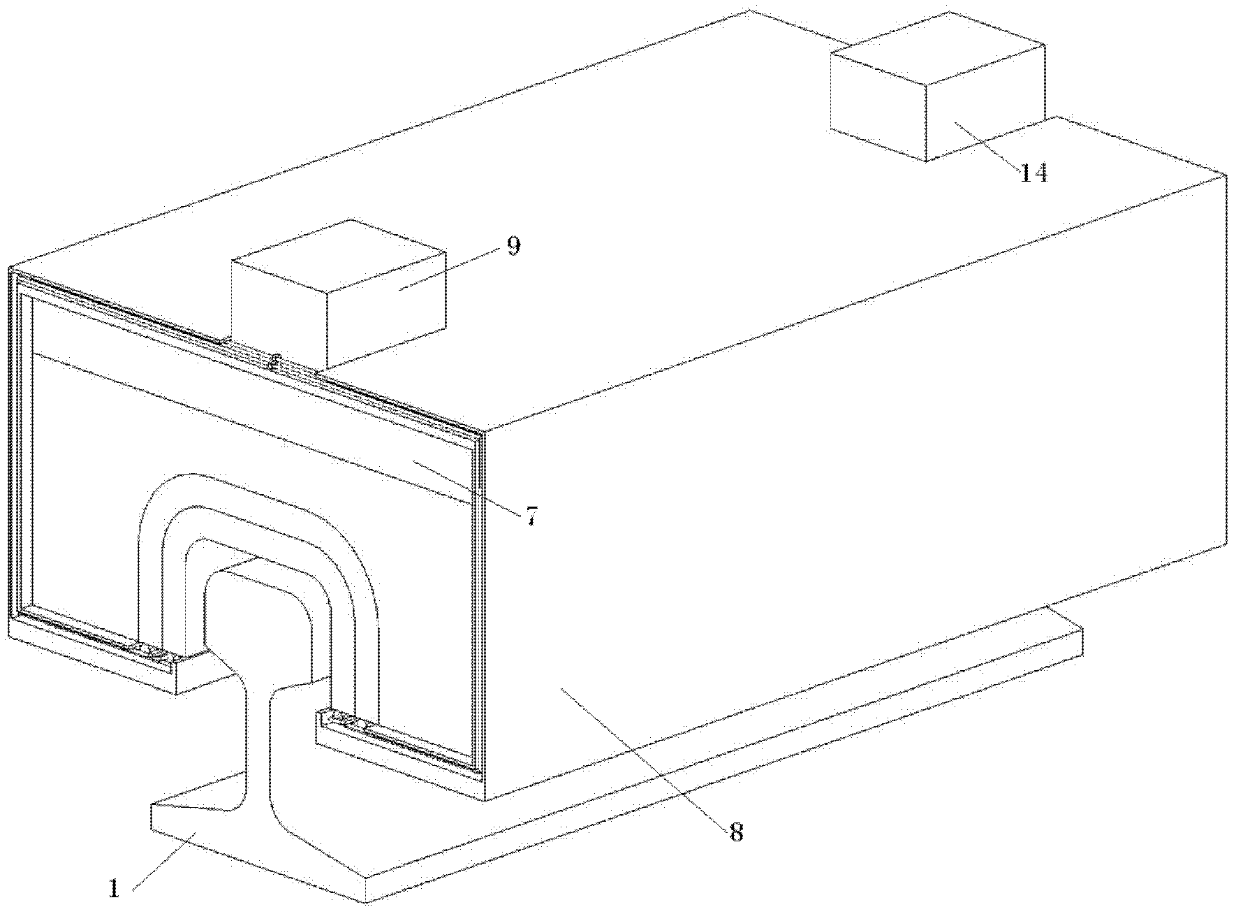
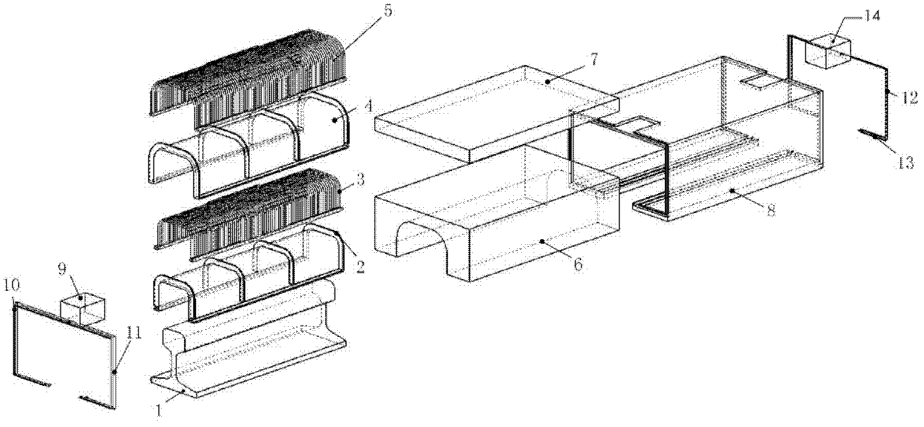
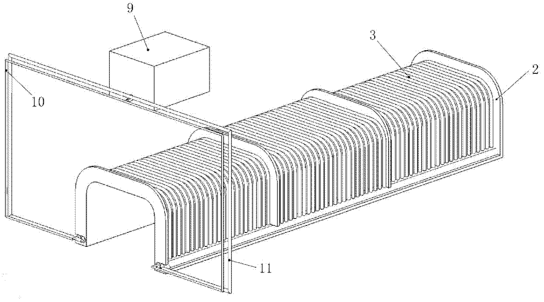
[0057] A rail damage detection device based on magnetostriction and longitudinal ultrasonic guided waves has the advantages of long detection distance, short detection time, real-time detection during online operation of a non-contact rail inspection vehicle, and early crack damage of the rail can be found. Its mechanical parts such as figure 1shown. Its appearance is a cuboid with an open lower end, the shape of the lower end opening is similar to the shape of the rail head, slightly larger than the rail to ensure its non-contact with the rail; the upper part is connected with the rail inspection vehicle. It includes inner layer wire holder 2, inner layer coil 3, outer layer wire holder 4, outer layer coil 5, yoke iron 6, permanent magnet 7, shell 8, current input port 9, electrical inner layer coil current input wire 10, inner Layer coil current output wire 11, outer coil current output wire 12, outer coil current loop wire 13, voltage output port 14, specifically as fig...


PUM


Abstract

The invention discloses a rail damage detection device and method based on magnetostriction and longitudinal ultrasonic guided wave, which are applied in the field of railway traffic nondestructive detection. The rail damage detection device comprises a shell, wherein an inner wire support, an inner coil, an outer wire support, an outer coil, a yoke and a permanent magnet are arranged in the shell; a current input port, an inner coil current input electric wire and an inner coil current output electric wire are arranged at one end of the shell; an outer coil current output electric wire, an outer coil current loop electric wire and a voltage output port are arranged at the other end of the shell; and the upper part of the shell is fixedly connected with a rail detection vehicle. The rail damage detection method comprises the following steps of: exciting induced electromotive force by utilizing magnetostriction and longitudinal ultrasonic guided wave, and indirectly measuring time and strength generated by a defect reflective waveguide signal according to the induced electromotive force, and further determining the destruction position and the destruction size. The rail damage detection device and method can be used for carrying out accurate detection on trace destruction inside and outside the rail, and have the advantages of long detection distance and high detection efficiency.

Description

technical field [0001] The invention relates to the field of rail transit non-destructive testing, in particular to a rail damage testing device and method based on magnetostrictive technology and longitudinal ultrasonic guided wave technology. Background technique [0002] At present, in the field of non-destructive testing of rail transit, most of the detection methods such as magnetic flux leakage method, infiltration method and eddy current method are used to detect the damage of rails. At the same time, people are still using ray method and ultrasonic method to monitor the degree of track damage. Now widely used is the track inspection vehicle technology. The detection system mainly integrates ultrasonic and electromagnetic induction detection technologies and optical sensors on the platform of the rear-mounted track detection vehicle. In addition, Imperial College London developed a piezoelectric sensor-based longitudinal ultrasonic guided wave rail damage detection ...

Claims


Application Information

Patent Timeline
Patent Type & Authority Applications(China)
IPC IPC(8): G01N29/09G01N29/07
Inventor 马宏伟宋振华
Owner JINAN UNIVERSITY
Why Eureka
Try Eureka