Optical fiber loop framework and winding method thereof

An optical fiber loop and skeleton technology, applied in Sagnac effect gyroscopes and other directions, can solve the problem that the advantages of quadrupole symmetry and improved winding method cannot be fully utilized, the influence of reciprocity winding process consistency, and the inability to guarantee each Layer turns consistency and other issues, to achieve the effect of efficient batch winding, automated process promotion, and reduced human intervention

Active Publication Date: 2012-07-11
武汉长盈通光电技术股份有限公司
View PDF3 Cites 17 Cited by
  • Summary
  • Abstract
  • Description
  • Claims
  • Application Information

AI Technical Summary

Problems solved by technology

[0004] The existing method to reduce the temperature sensitivity of the fiber optic gyroscope is to use various symmetrical winding methods with enhanced reciprocity to wind the optical fiber ring with rectangular cross-section on the basis of the rectangular cross-section bearing surface, so that the temperature field and additional thermal stress distribution in the optical fiber are as symmetrical as possible. , For example, in the Chinese invention patent application "A Method for Encircling Optical Fiber" with the publication number CN 102116623 A, the optical fiber gyroscope coil wound by the four-pole symmetrical winding method has shown a better temperature than the original spiral winding method. characteristics, but there is still a gap between the existing four-pole symmetrical winding method and the ideal complete reciprocal four-pole symmetrical winding, because the consistency of the number of turns in each layer cannot be guaranteed in the actual winding process
As shown in the above literature, th...

Method used


Image

  • Optical fiber loop framework and winding method thereof
  • Optical fiber loop framework and winding method thereof
  • Optical fiber loop framework and winding method thereof

Examples


Embodiment Construction

[0026] Below in conjunction with accompanying drawing, specific embodiment of the present invention is described in further detail:

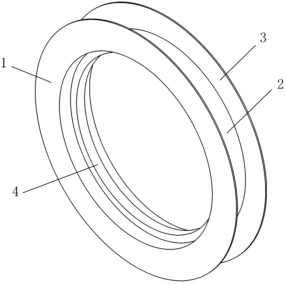
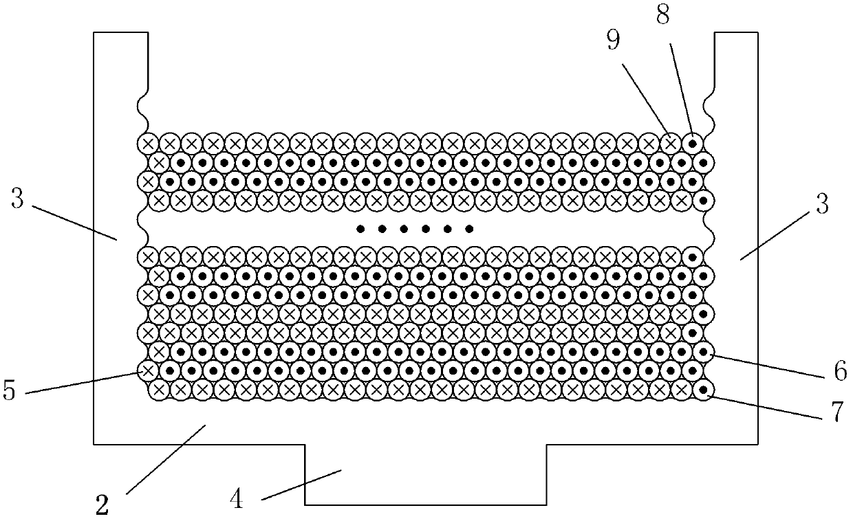
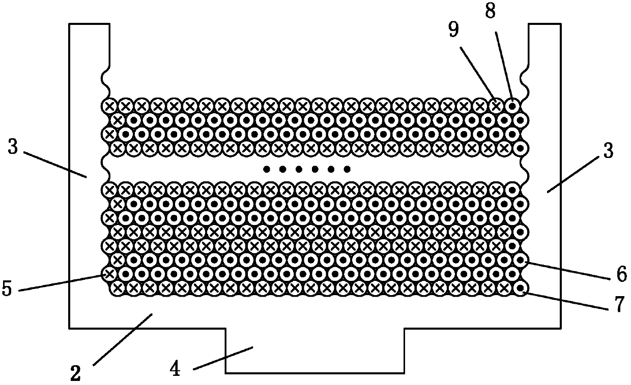
[0027] Such as figure 1 and figure 2 As shown, an optical fiber ring frame of the present invention includes a frame body 1 with an annular groove on the rim, and the groove bottom 2 of the frame body 1 is provided with several fiber grooves along the winding direction of the optical fiber. The distance is consistent with the diameter of the optical fiber to be wound; the side wall 3 of the skeleton body 1 is provided with several convex and concave positioning protrusions and positioning grooves along the winding direction of the optical fiber. And on the two side walls 3, the convex and concave are opposite at the same distance from the bottom 2 of the groove. In order to facilitate the subsequent use of the optical fiber ring, a flange 4 is provided on the inner surface of the skeleton body 1, which can be used for fixing with other compo...


PUM


Abstract

The invention provides an optical fiber loop framework comprising a framework body the rim of which is provided with an annular groove. A plurality of optical fiber grooves are arranged at the bottom of the groove of the framework body along an optical fiber winding direction; and the distance of the adjacent optical grooves is consistent with the diameter of an optical fiber to be wound. A plurality of positioning bulges and positioning grooves, which are convex and concave alternatively, are arranged on the lateral wall of the framework body along the optical fiber winding direction; and the diameters of the positioning bulges and the positioning grooves are opposite to positions, having equal distanced with the bottom of the groove, on the two lateral walls of the diameter of the optical fiber to be wound in a convex-concave mode. An optical loop winding method using the framework comprises the following steps of: 1) calculating and preparing the optical fiber with enough length and remaining a tail fiber enough; 2) marking the both end points and central point of the optical fiber, and marking symmetrical central points on the outer wall at the right side of the framework; 3) tightly adhering the optical fiber to the inner side of the right wall of the framework, aligning the left and right symmetrical central points of the optical fiber to the symmetrical central points with the symmetrical central point mark on the outer wall of the framework, and winding the optical fiber by using a four-pole symmetrical winding method until the two sections of optical fibers are wound to the respective final points respectively; 4) fixing the tail fiber on the framework; and 5) carrying out later-period curing process.

Description

technical field [0001] The invention relates to an optical fiber gyroscope, in particular to an optical fiber loop skeleton and its winding method. Background technique [0002] Born in 1976, the fiber optic gyroscope is an all-solid-state inertial instrument based on the Sagnac effect. Since its inception, it has attracted the attention of major countries in the world for its outstanding performance characteristics and good application prospects. The strapdown inertial system based on fiber optic gyroscope has many advantages such as high reliability, long life, fast start-up, low power consumption, and relatively simple production process, so it has very important use value and promotion in military equipment and civilian fields. prospect. [0003] Since there are obvious differences between the fiber optic gyroscope and other types of gyroscopes in terms of working principle, structural composition, manufacturing method, performance indicators, testing and evaluation, et...

Claims


Application Information

Patent Timeline
IPC IPC(8): G01C19/72
Inventor 何元兵汪洪海皮亚斌
Owner 武汉长盈通光电技术股份有限公司
Why Eureka
Try Eureka