
In-plane switching mode liquid crystal display
A liquid crystal display, internal switching technology, applied in the direction of instruments, optics, nonlinear optics, etc., can solve problems such as difficult to manufacture thin products, low economic benefits, changes in polarization and color, and achieve the effect of ensuring a wide viewing angle
- Summary
- Abstract
- Description
- Claims
- Application Information
AI Technical Summary
Problems solved by technology
Method used
Image

Examples
example 1
[0087] According to the actual measured data of each optical film of the present invention, liquid crystal cell and backlight module with figure 1 The stacked structure shown was applied to TECH WIZ LCD 1D (Sanayi System Co., Ltd., Korea). described in detail below figure 1 Structure.
[0088] Starting from the backlight module 40 side, a lower polarizing plate 20, an in-plane switching mode liquid crystal cell 30 (when no voltage is applied, the liquid crystal cell has a 0 ° liquid crystal alignment) and the upper polarizing plate 10, wherein the lower polarizing plate 20 is formed by laminating the second compensation film 24, the polarizing plate 21 and the protective film 23 from the liquid crystal cell 30 side, and the lower polarizing plate 20 is formed by laminating the second compensation film 24 from the liquid crystal cell 30 side. A compensation film 14 , polarizing plate 11 and protective film 13 form the upper polarizing plate 10 .
[0089] As for the liquid cr...
example 2
[0108] Although the configuration is the same as in Example 1, the thickness of the cell is adjusted so that at a wavelength of 589 nm, the retardation of the liquid crystal cell is 380 nm, and the second compensation film 24 has an in-plane retardation (R0) of 200 nm and a refractive index ratio (NZ ), and the first compensation film 14 has an in-plane retardation (R0) of 70 nm and a refractive index ratio (NZ) of -1.9, and an in-plane switching mode is fabricated using the second compensation film 24 and the first compensation film 14 LCD Monitor.
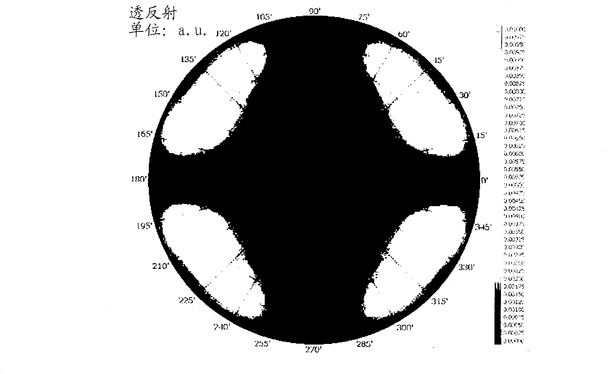
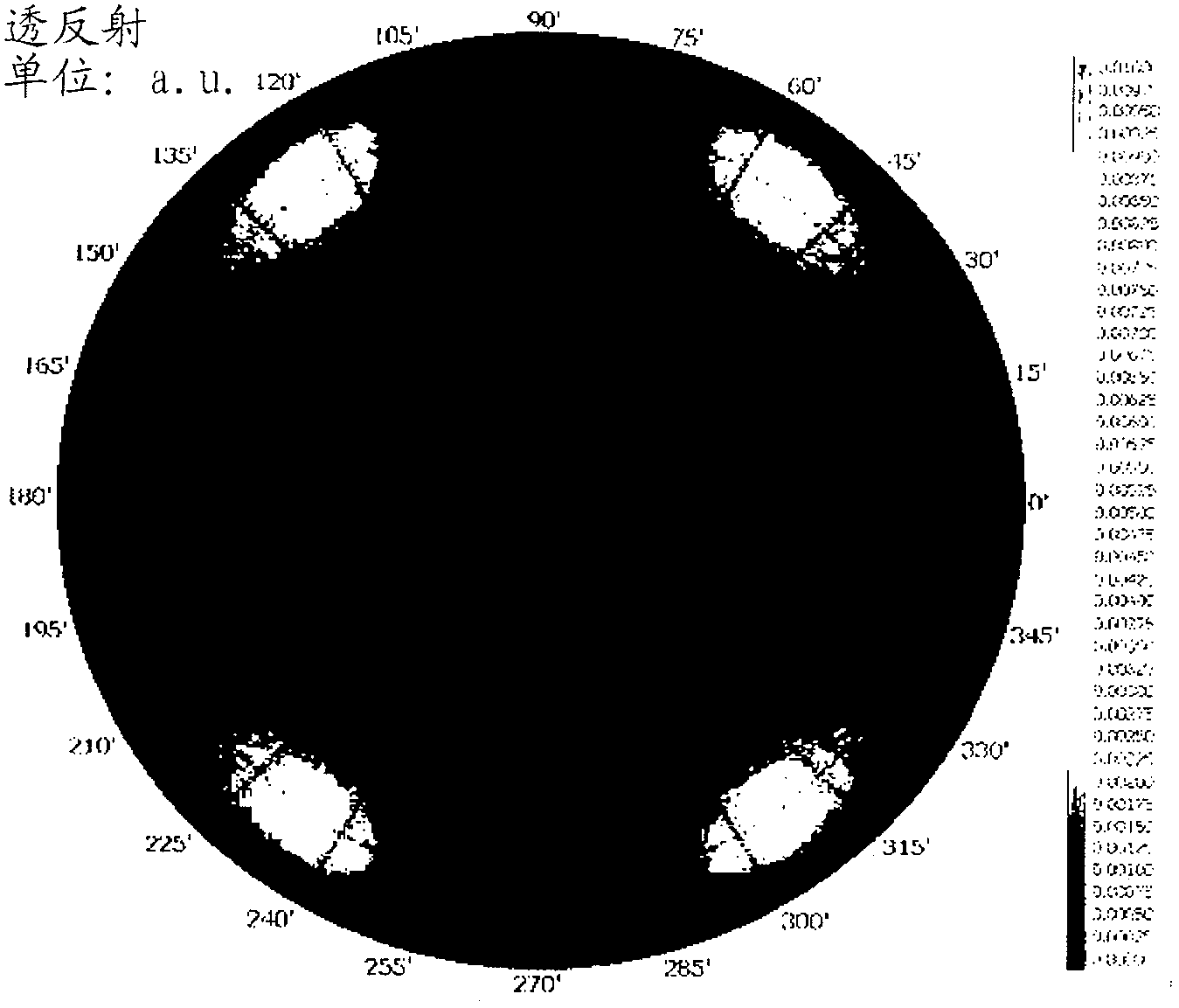
[0109] The variation of the polarization state of an in-plane switching-mode liquid crystal display on a Poincaré sphere depending on wavelength versus Figure 5 Similarly, moreover, the transmittance results for all light directions are the same as Figure 7 same. able to pass Figure 7 Confirm that since the blue portion is wider at the center, a wider viewing angle is ensured.
example 3
[0111] Although the configuration is the same as in Example 1, the thickness of the cell is adjusted so that at a wavelength of 589 nm, the phase difference of the liquid crystal cell is 380 nm, and the second compensation film 24 has an in-plane retardation (R0) of 150 nm and a refractive index ratio (NZ ), and the first compensation film 14 has an in-plane retardation (R0) of 150 nm and a refractive index ratio (NZ) of -1, and an in-plane switching mode is fabricated using the second compensation film 24 and the first compensation film 14 LCD Monitor.
[0112] The variation of the polarization state of an in-plane switching-mode liquid crystal display on a Poincaré sphere depending on wavelength versus Figure 5 Similarly, moreover, the transmittance results for all light directions are the same as Figure 8 same. able to pass Figure 8 Confirm that since the blue portion is wider at the center, a wider viewing angle is ensured.
PUM
| Property | Measurement | Unit |
|---|---|---|
| In-plane delay | aaaaa | aaaaa |
| In-plane delay | aaaaa | aaaaa |
Abstract
Description
Claims
Application Information