Method and device for correcting coordinate positions of multiple image sensors

An image sensor and coordinate position technology, applied in the direction of measuring devices, optical devices, instruments, etc., can solve the problems that affect the manufacturing precision of optoelectronic products, it is difficult to meet the detection precision, and the improvement of detection precision has no significant effect, etc.

Inactive Publication Date: 2015-04-22
姚福来
View PDF6 Cites 0 Cited by
  • Summary
  • Abstract
  • Description
  • Claims
  • Application Information

AI Technical Summary

Problems solved by technology

[0004] However, due to the extremely high manufacturing precision of current optoelectronic products, the above-mentioned method of using the mechanical origin to correct the coordinate positions of the image sensors will easily cause the error of each image sensor when correcting the coordinate positions of multiple image sensors. However, the slight error is enough to affect the manufacturing accuracy of optoelectronic products; in addition, the method of obtaining the coordinate position by using the image sensor to sense the single orientation of the object to be measured is obviously It has been difficult to meet the demand for detection precision at the present stage; in addition, although there are existing methods on the market that respectively configure image sensors in multiple directions of an object for sensing, the image sensors operate independently Therefore, the coordinate positions of each image sensor do not have the ability to be mobilized synchronously, and no method for correcting the coordinate positions of the image sensors is proposed
[0005] Moreover, there is another technology on the market that uses a mask to correct the coordinate position of the image sensor in a single orientation of the object, but the image sensor in the single orientation of the object does not have a significant effect on the improvement of detection precision.

Method used


Image

  • Method and device for correcting coordinate positions of multiple image sensors
  • Method and device for correcting coordinate positions of multiple image sensors
  • Method and device for correcting coordinate positions of multiple image sensors

Examples


Embodiment Construction

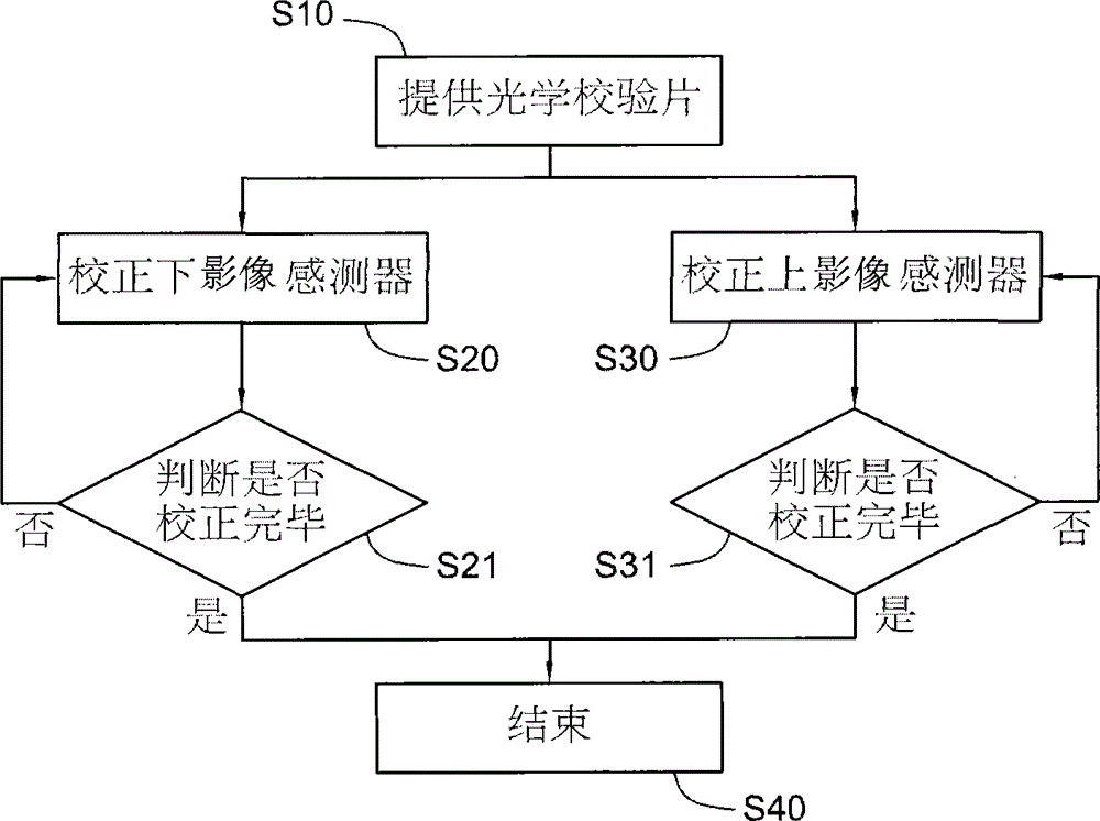
[0032] first look figure 1 As shown, reveals the flow chart of the first embodiment of the present invention, and coordinates Figure 2 to Figure 4 The method for calibrating the coordinate positions of multiple image sensors in the present invention includes the following implementation steps:

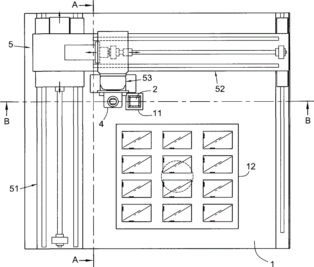
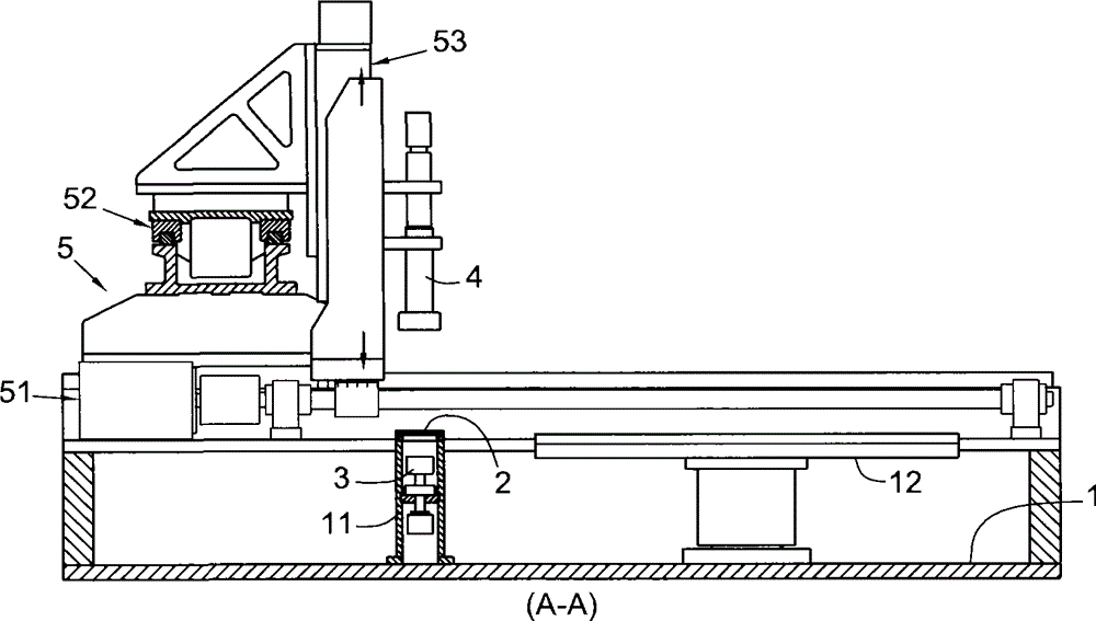
[0033] In step S10, a photomask 2 is provided on a testing station 1 (cooperating with Figure 5 and Figure 6 shown), the mask 2 has a light-transmitting pattern 21, and the light-transmitting pattern 21 has more than one light-transmitting block 211 and more than one shielding block 212; Type holder 11, the photomask 2 is fixed on the top of holder 11. In addition, the testing platform 1 is provided with a receiving tray 12 on which the objects to be tested can be placed.

[0034] In step S20, use the lower image sensor 3 on the detection table 1 to sense the light-transmitting pattern 21 (with Figure 5 and Figure 6 shown), by identifying the light-transmitting block 211 and...


PUM


Abstract

The invention discloses a method and a device for correcting coordinate positions of multiple image sensors. The device comprises a photomask on a detection platform, a lower image sensor and an upper image sensor. A translucent pattern is arranged on the photomask. The lower image sensor is enabled to sense the translucent pattern from below the photomask, so as to correct the coordinate position of the lower image sensor. The upper image sensor is enabled to sense the translucent pattern from above the photomask, so as to correct the coordinate position of the upper image sensor. In this way, the coordinate positions of the upper and lower image sensors can be adjusted synchronously.

Description

technical field [0001] The invention provides a method for calibrating the coordinate positions of multiple image sensors, and particularly relates to calibrating the coordinate positions of multiple image sensors of a detection device by using a mask. The invention also provides a detection device with a plurality of image sensors. Background technique [0002] Industrial inspection equipment is usually equipped with an image sensor, such as an image CCD (Charge Coupled Device) sensor, most of which can move vertically, laterally, and vertically on the inspection table of the inspection equipment. And the top surface image of the object to be tested on the detection table can be sensed from top to bottom. [0003] It is known that the above-mentioned image sensor can usually be externally connected to a computer, and the coordinate position of the image sensor can be calculated by the computer, and then the coordinate position of the object to be measured sensed by the ima...

Claims


Application Information

Patent Timeline
Patent Type & Authority Patents(China)
IPC IPC(8): G01B11/00
Inventor 姚福来
Owner 姚福来
Why Eureka
Try Eureka