
Exhaust gas diffuser of gas turbine
A gas turbine and diffuser technology, which is applied to the exhaust port of the power unit, machine/engine, steam storage, etc., can solve the problems of supporting column aerodynamic force, guide body length, etc., and achieve the tendency of reducing vibration and effectively Space, space-saving effect
- Summary
- Abstract
- Description
- Claims
- Application Information
AI Technical Summary
Problems solved by technology
Method used
Image

Examples
Embodiment Construction
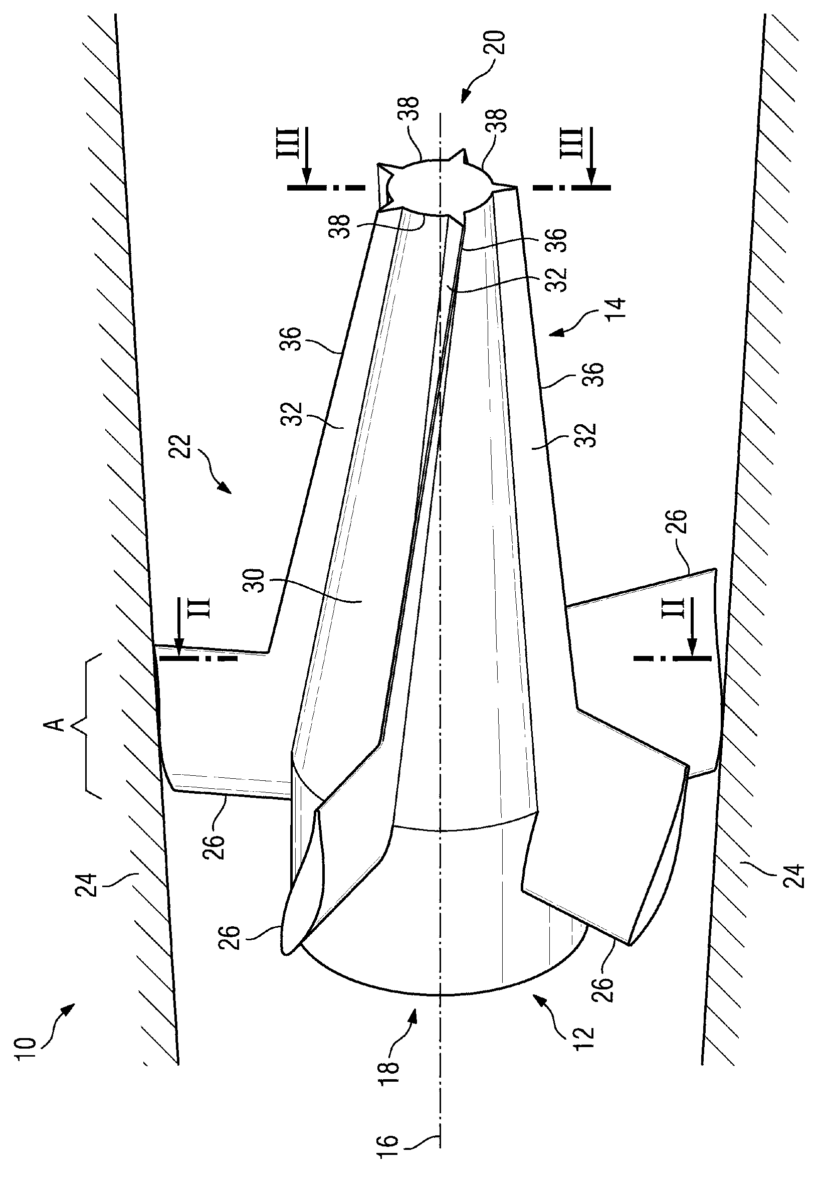
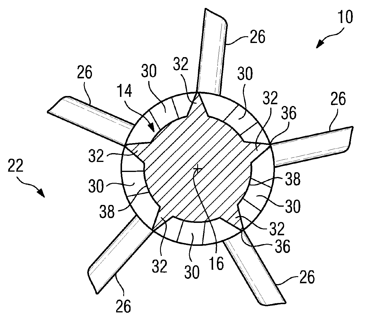
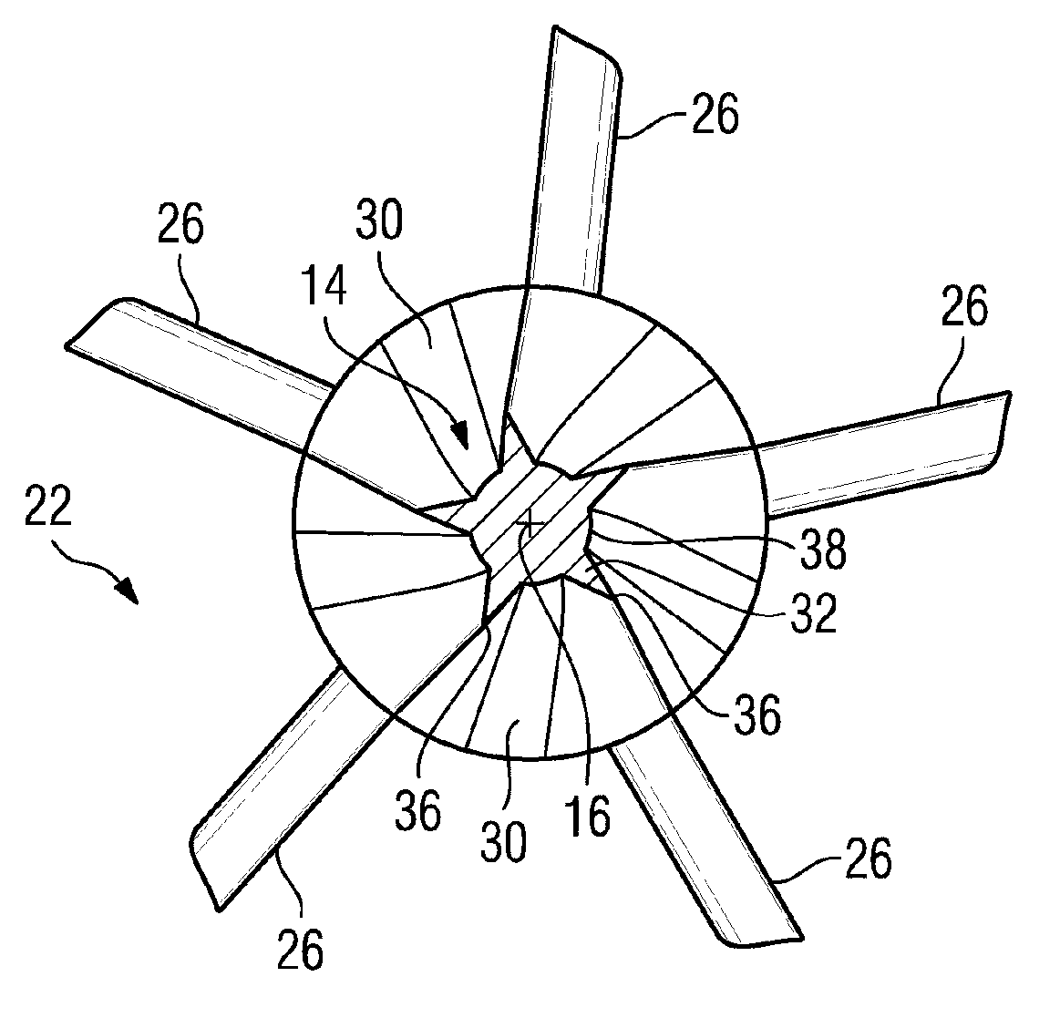
[0016] exist figure 1 shows a longitudinal sectional view of an exhaust diffuser 10 for a gas turbine, wherein a perspective view of a star-shaped support 12 arranged in the center of the exhaust diffuser 10 is shown for the turbine-side The gas turbine rotor and the guide body 14 arranged on the star support are supported. The exhaust gas diffuser 10 has a centrally located center axis 16 which extends from an inflow-side end 18 to an outflow-side end 20 . A flow channel 22 is provided in the exhaust gas diffuser 10 , the cross section of which flow channel is perpendicular to the center axis and has an annular contour. In this case, the flow channel 22 is delimited by a radially outer outer wall 24 . The guide body 14 is arranged in the center of the exhaust gas diffuser 10 , ie in the region of its center axis 16 , and here is the radially inner boundary of the flow channel 22 . In this case, the guide body 14 is supported by five bearing struts 26 distributed uniformly ...
PUM
 Abstract
Description
Claims
Application Information