
Attachment structure of lighting device

A lighting device and structure technology, which can be applied to lighting devices, lighting devices, components of lighting devices, etc., and can solve problems such as appearance deterioration.

Active Publication Date: 2015-06-17
PANASONIC CORP
View PDF5 Cites 0 Cited by
  • Summary
  • Abstract
  • Description
  • Claims
  • Application Information

AI Technical Summary

Problems solved by technology

[0003] However, in the installation structure of the above-mentioned appliance type lighting, since the lighting lamp is installed from the indoor side, the appearance size of the lower opening of the lighting box and the louver installed thereon when viewed from the indoor side become large, and the presence of the louver becomes large. Stressed, the appearance may deteriorate

Method used


Image

  • Attachment structure of lighting device
  • Attachment structure of lighting device
  • Attachment structure of lighting device

Examples


Embodiment Construction

[0023] Hereinafter, embodiments of the present invention will be described with reference to the drawings.

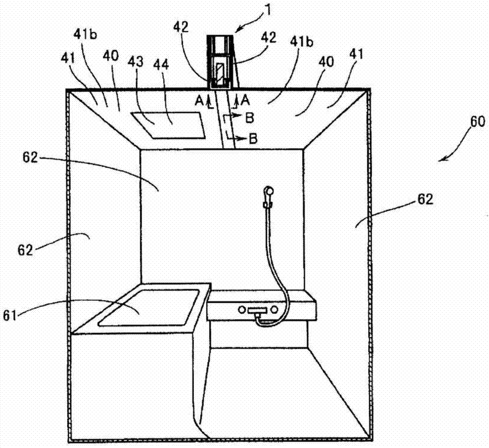
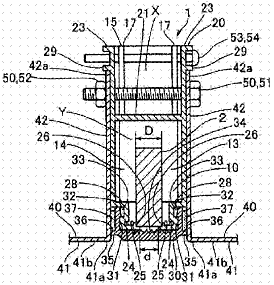
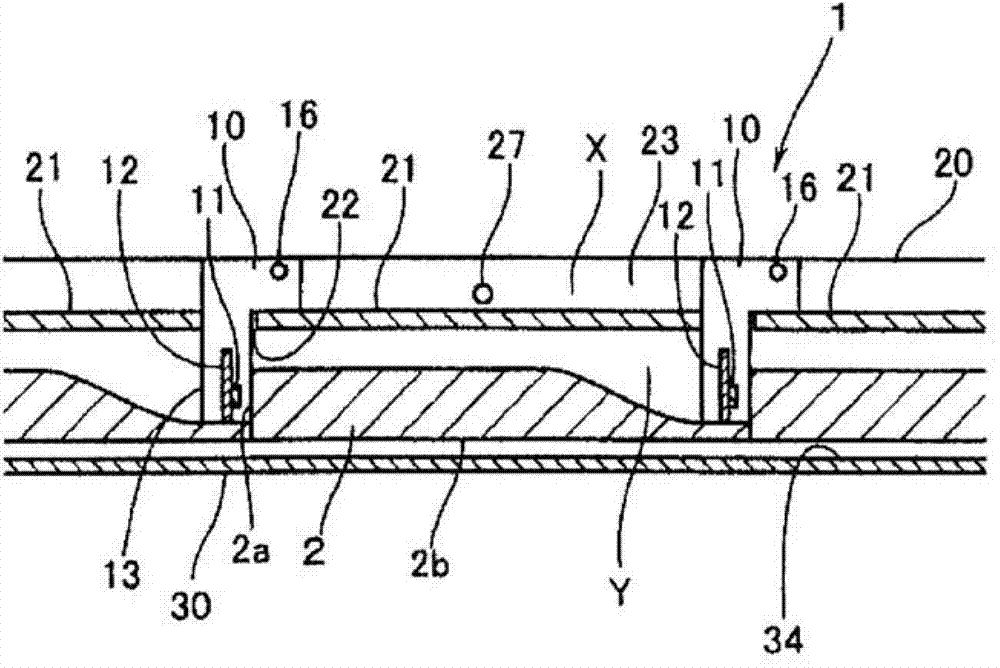
[0024] Figure 1A It is a perspective view showing one embodiment of the mounting structure of the lighting device of the present invention, Figure 1B yes Figure 1A The A-A line section view. figure 2 yes Figure 1A B-B line sectional view. image 3 is a perspective view of the light source unit. Figure 4 It is an exploded perspective view of the lighting device. Figure 5 It is an exploded perspective view illustrating the attachment of the light source unit to the cabinet, Image 6 It is an exploded perspective view illustrating attachment of the lighting device.

[0025] The ceiling member 40 is a constituent member of a ceiling such as a bathroom unit. In this embodiment, two ceiling members 40 and 40 are used to constitute the ceiling of the bathroom unit 60 (see Figure 1A ). The ceiling member 40 is formed in a rectangular shape from metal such as a stee...


PUM


Abstract

In disclosed attachment structure of a lighting device, an elongated lighting device is incorporated between adjacent ceiling members. The lighting device is provided with: a light source; a light-guide member that guides light emitted from the light source to below the ceiling; and an elongated case body that houses the light source and the light-guide member. The light-guide member has: a light entrance surface that is elongated and that is at one end surface in the lengthwise direction; and a light-emitting surface that radiates illuminating light at one side surface in the lengthwise direction. The light source is provided facing the entrance surface of the light-guide member. Adjacent ceiling members are provided with a first and second holding piece that each protrude towards the rear of the ceiling from a pair of side edges that face each other. The lighting device is held in a manner so as not to protrude from the ceiling surface between the first and second holding pieces that face each other of adjacent ceiling members, and is attached to adjacent ceiling members by means of an anchor that successively penetrates the first holding piece, the case body, and the second holding piece in the given order at a position that is at least above the light-guide member.

Description

technical field [0001] The present invention relates to an installation structure of a lighting device. Background technique [0002] The lighting installed on the ceiling is usually instrument-type lighting such as downlights or chandeliers. Most of these appliance-type lighting protrude from the ceiling surface, and this appliance-type lighting has a strong sense of presence, etc., and rarely takes the appearance of the interior space into consideration. Here, a functional appliance-type lighting mounting structure has been proposed to improve lighting presentation effects in bathrooms and the like and to enhance enjoyment of bathing and the like (see Japanese Utility Model Laid-Open No. 61-178215). Specifically, a plurality of lighting boxes that are L-shaped in side view and open at the bottom are installed by connecting the vertical part side and the horizontal part side to the ceiling. Shutters are installed on the lower opening of the body. In the installation stru...

Claims


Application Information

Patent Timeline
Patent Type & Authority Patents(China)
IPC IPC(8): F21S8/02F21S2/00F21V21/04F21V33/00F21Y101/02
CPCF21S8/026F21S8/04F21V33/006F21Y2103/10F21Y2115/10
Inventor 大野达司小泉秀树田中敏裕
Owner PANASONIC CORP
Learn More