air conditioner

An air-conditioning device and air-conditioning technology, which is applied in air-conditioning systems, space heating and ventilation, space heating and ventilation details, etc., can solve the problems that it is difficult to obtain the sense of unity between indoor units and columns, and achieve the goal of improving the sense of unity Effect

Active Publication Date: 2020-09-01
TOSHIBA CARRIER CORP
View PDF4 Cites 0 Cited by
  • Summary
  • Abstract
  • Description
  • Claims
  • Application Information

AI Technical Summary

Problems solved by technology

[0005] At the same time, it is easy to cause an unnatural shape like installing the indoor unit on the existing column from the rear, and it is difficult to obtain a sense of unity between the indoor unit and the column

Method used


Image

  • air conditioner
  • air conditioner
  • air conditioner

Examples


no. 1 Embodiment approach

[0142] Below, refer to Figure 1 to Figure 16 The first embodiment will be described.

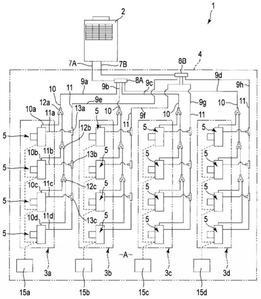
[0143] figure 1 It is a circuit diagram showing a piping system of an air conditioner 1 used for localized cooling / heating of a large-scale space such as a production plant, a vehicle factory, and the like, for example. Such as figure 1 As shown, the air conditioner 1 includes an outdoor unit 2 and first to fourth indoor unit units 3a, 3b, 3c, and 3d as main components.

[0144] The outdoor unit 2 is fixed outside the building 4 of a factory, for example, and accommodates various refrigeration cycle equipment such as a compressor for compressing refrigerant, a heat exchanger, and an accumulator. The first to fourth indoor unit units 3 a , 3 b , 3 c , and 3 d are installed in an air-conditioned work area A inside the building 4 . The first to fourth indoor unit units 3 a , 3 b , 3 c , and 3 d each include four indoor units 5 .

[0145] The liquid-side main pipe 7A connected to the outdo...

no. 2 Embodiment approach

[0259] Figure 18 to Figure 24 The second embodiment is disclosed.

[0260] The difference between the second embodiment and the first embodiment is mainly in the structure of the frame 200 that supports the first to fourth indoor unit units 3 a , 3 b , 3 c , and 3 d on the pillar body 80 . The configuration other than that is basically the same as that of the first embodiment. Therefore, in the second embodiment, the same components as those in the first embodiment are assigned the same reference numerals, and descriptions thereof are omitted.

[0261] Such as Figure 19 to Figure 21 As shown, the frame 200 has four first vertical mullions 201a, 201b, 201c, and 201d, a plurality of first to fourth horizontal mullions 202a, 202b, 202c, and 202d, and first to fourth unit support portions. 203a, 203b, 203c, 203d as main elements.

[0262] The first vertical mullion 201a, 201b, 201c, 201d includes, for example, an angle steel having an L-shaped cross-sectional shape, and has ...


PUM


Abstract

The air conditioner according to the present invention includes: a frame that is assembled to a base structure located in a space to be air-conditioned and surrounds an outer peripheral portion of the base structure; a plurality of indoor units mounted to the frame so as to face the outer peripheral portion of the base structure, a heat exchanger for heat exchanger is formed between the air and a refrigerant, and a suction inlet is formed to guide the air to the heat exchanger; a plurality of panels mounted on the frame so as to surround the outer peripheral portion of the base structure in association with the indoor unit; when the indoor unit and the panel are mounted on the frame, a suction passage is defined in the space around the base structure from the space to be air-conditioned, and the indoor unit suction inlet is connected with the suction passage. The air conditioner of the present invention can suppress the presence of the indoor unit and improve the integral of the indoor unit and the base structure.

Description

technical field [0001] Embodiments of the present invention relate to an air conditioner in which a plurality of indoor units (units) are installed around a basic structure such as a column. Background technique [0002] For example, in a large-scale production plant, an air conditioner is used that locally cools / heats work areas (areas) scattered within the plant building. [0003] This type of air conditioner includes a plurality of indoor units that blow air with adjusted temperature or humidity toward a working area. The indoor unit is installed, for example, on the outer peripheral portion of the column to surround the column that becomes the framework of the building. [0004] When a plurality of indoor units are installed around the cylinder, duets leading air to the heat exchangers of the indoor units and pipes leading refrigerant to the heat exchangers may be exposed in the work area. Since ducts and pipes are routed around the column, it is undeniable that the pr...

Claims


Application Information

Patent Timeline
Patent Type & Authority Patents(China)
IPC IPC(8): F24F5/00F24F13/00F24F13/30F24F13/20
CPCF24F5/0003F24F13/00F24F13/20F24F13/30
Inventor 奥山航辉尾崎健田辺厚寺崎明
Owner TOSHIBA CARRIER CORP
Why Eureka
Try Eureka