Underbody Structure

A car body and structure technology, which is applied in the direction of superstructure, superstructure sub-assembly, and connection between superstructure sub-assemblies, to achieve the effect of improving the sense of unity, improving strength and supporting rigidity

Active Publication Date: 2021-12-28
MAZDA MOTOR CORP
View PDF7 Cites 0 Cited by
  • Summary
  • Abstract
  • Description
  • Claims
  • Application Information

AI Technical Summary

Problems solved by technology

[0005] In Patent Document 1, from the viewpoint of improving the sense of unity between the vehicle body and the seat, there is still room for further improvement in the support rigidity of the vehicle body for supporting the seat rail.

Method used


Image

  • Underbody Structure
  • Underbody Structure
  • Underbody Structure

Examples


Embodiment Construction

[0039] A lower vehicle body structure according to an embodiment of the present invention will be described below with reference to the drawings.

[0040] [overall composition]

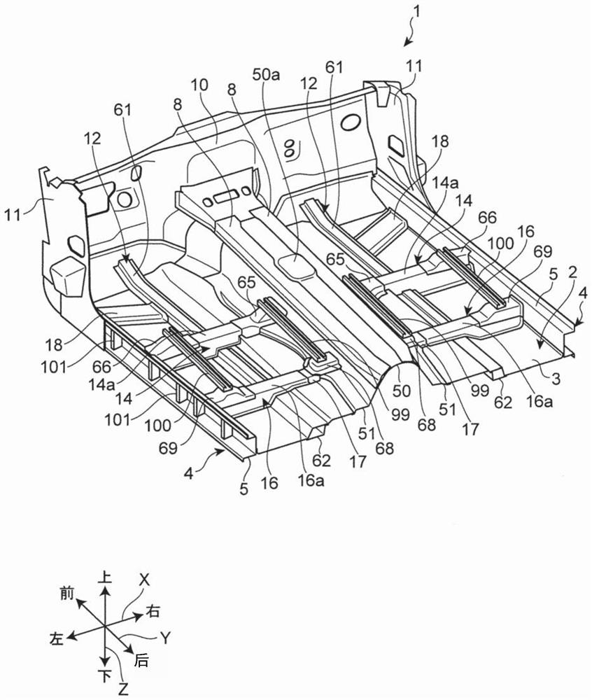
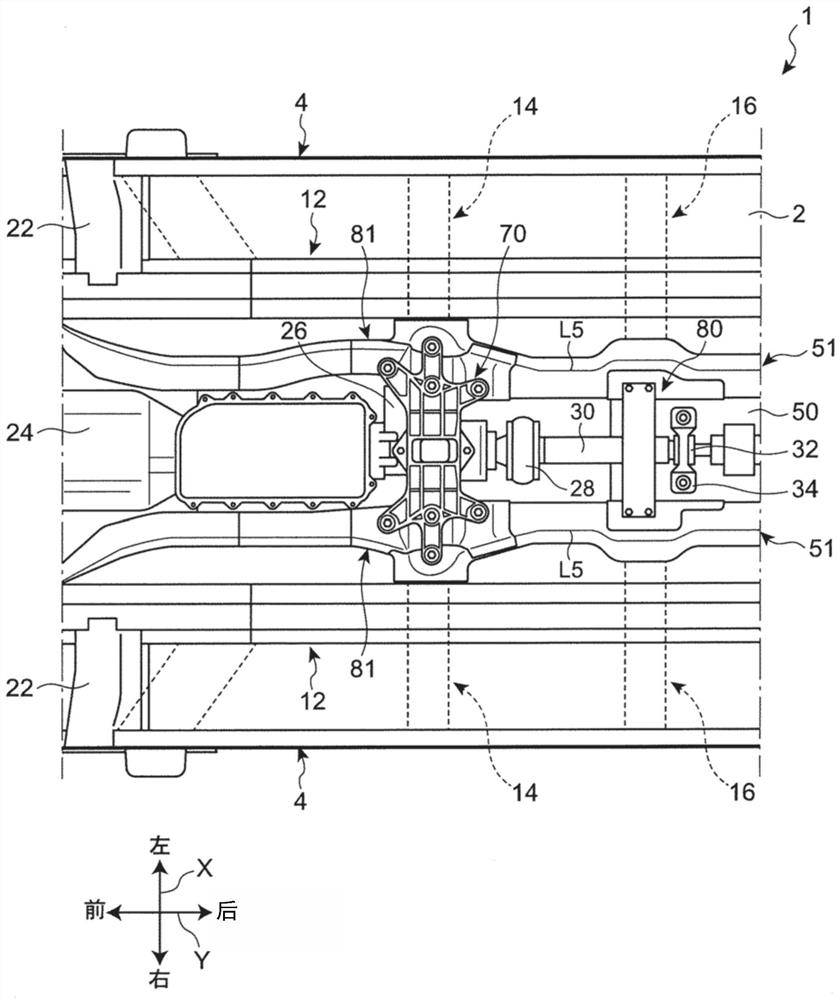
[0041] figure 1 It is a perspective view showing the lower vehicle body structure of this embodiment. figure 2 It is a plan view showing the structure of the lower vehicle body. image 3 It is a bottom view showing the structure of the lower body. In the following description, the vehicle width direction, the vehicle front-rear direction, and the vehicle vertical direction of the automobile 1 provided with the lower body structure of the present embodiment may be referred to as X direction, Y direction, and Z direction, respectively.

[0042] refer to figure 1 The automobile 1 provided with the lower body structure of this embodiment includes: a vehicle body floor 2 constituting the floor of the interior space of the vehicle compartment; a pair of sides extending in the Y direction along both sides...


PUM


Abstract

Provided is a lower vehicle body structure that improves the support rigidity of a vehicle body floor for supporting seat rails. The lower vehicle body structure of the present invention includes: a vehicle body floor (2); a first floor beam (14) extending along the vehicle width direction and having a closed cross-section structure; a second floor beam (16) parallel to the vehicle front and rear direction. The first floor beams (14) are arranged at intervals and have a closed cross-sectional structure along the vehicle width direction; the side beams (4) are arranged at the ends of the vehicle body floor (2) in the vehicle width direction and along the vehicle front-rear direction extending and having a closed cross-sectional structure; the floor frame (12), which is arranged on the inner side in the vehicle width direction compared with the side beam (4), extends along the vehicle front-rear direction and has a closed cross-sectional structure; and the mounting parts (65, 66, 68, 69), for installing the seat to the vehicle body. Mounting members (65, 66, 68, 69) are fixed to the edge beams (4), the first floor beam (14), and / or said second floor beam (16).

Description

technical field [0001] The present invention relates to underbody construction. Background technique [0002] A floor beam extending along the vehicle width direction and a floor frame extending along the vehicle front-rear direction are arranged above the vehicle body floor of the automobile to increase the rigidity of the vehicle body. In addition, seat rails that guide the sliding movement of the seats are generally provided on the vehicle body floor so as to extend in the front-rear direction. Seat rails are usually fixed to the vehicle body via highly rigid brackets. Accordingly, it is possible to stably support a heavy seat. [0003] As disclosed in Patent Document 1, in order to secure mounting rigidity in fixing a seat rail, a floor cross member or a floor frame provided on a vehicle body floor may receive a load. [0004] Patent Document 1: Japanese Patent Laid-Open No. 2010-228482 [0005] In Patent Document 1, from the viewpoint of improving the sense of unity...

Claims


Application Information

Patent Timeline
Patent Type & Authority Patents(China)
IPC IPC(8): B62D25/20
CPCB62D25/20B62D25/025B60N2/015B62D25/2036B62D27/02
Inventor 枣裕贵影山和宏戎本圭佑松冈秀典
Owner MAZDA MOTOR CORP
Why Eureka
Try Eureka