Cage-shaped rotor magnetic coupling capable of regulating speed

A magnetic coupling and cage rotor technology, applied in the direction of asynchronous induction clutch/brake, etc., can solve the problems of unsuitable for high-power electromechanical equipment transmission, poor reliability, long design cycle, etc., to facilitate serial design and manufacture , Reduce design and production costs, simple processing and assembly

Inactive Publication Date: 2013-02-06
葛研军
View PDF5 Cites 9 Cited by
  • Summary
  • Abstract
  • Description
  • Claims
  • Application Information

AI Technical Summary

Problems solved by technology

[0004] At present, magnetic couplers are generally disc-type, sleeve-type and cage-type sleeve-type. When the disc-type and sleeve-type magnetic couplers are running, the slip rate is large, and large eddy currents are generated in the copper disc or copper sleeve, which leads to the failure of the coupler system. The heat loss is large, the efficiency is low, and it is not suitable for high-power electromechanical equipment transmission
The cage bars and silicon steel laminations in the cage-type sleeve-type magnetic coupler need to be redesigned. The relevant performance parameters have not been tested in a large number of practices, and the reliability is poor, and the design cycle is long and the manufacturing cost is high. In addition, the cage-type sleeve type magnetic force The coupler generally needs to install an isolation sleeve between the permanent magnet rotor and the cage rotor. In addition to increasing the design and manufacturing costs, it also causes serious magnetic flux leakage between the permanent magnet rotor and the cage rotor poles, and the operating efficiency is low.

Method used


Image

  • Cage-shaped rotor magnetic coupling capable of regulating speed
  • Cage-shaped rotor magnetic coupling capable of regulating speed
  • Cage-shaped rotor magnetic coupling capable of regulating speed

Examples


Embodiment Construction

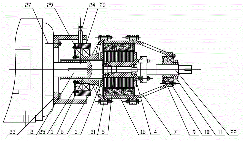
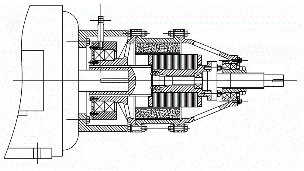
[0041] The present invention will be described in further detail below in conjunction with the accompanying drawings. Such as Figure 1-13 As shown, an adjustable speed cage rotor magnetic coupler includes a power input shaft 1, a coupling device, a permanent magnet outer rotor assembly, a cage inner rotor assembly, a power output shaft 22 and a mechanical speed regulating device; The permanent magnet outer rotor assembly is set on the outside of the cage-type inner rotor assembly, and there is a uniform air gap between the two; the permanent magnet outer rotor assembly is connected with the power input shaft 1 through a connecting device, and the cage The inner rotor assembly is connected to the load through the power output shaft 22, and the mechanical speed regulating device is installed on the outside of the right casing 7, which can drive the connecting device and the permanent magnet outer rotor assembly to move axially;

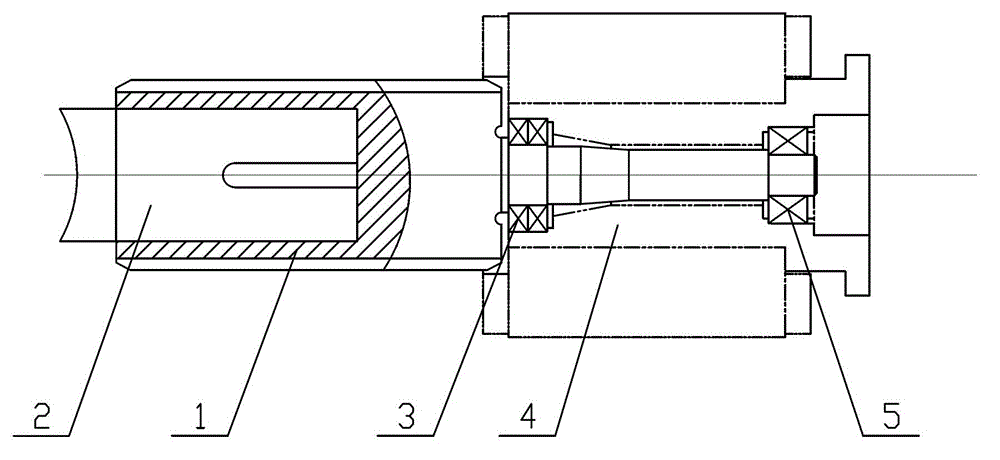
[0042] The power input shaft 1 is a stepped sha...


PUM


Abstract

The invention discloses a cage-shaped rotor magnetic coupling capable of regulating speed. The cage-shaped rotor magnetic coupling comprises a power input shaft, a connection device, a permanent magnet outer rotor assembly, a cage-shaped inner rotor assembly, a power output shaft and a mechanical speed regulating device, the permanent magnet outer rotor assembly is sleeved outside the cage-shaped inner rotor assembly, and even air gaps are arranged between the permanent magnet outer rotor assembly and the cage-shaped inner rotor assembly. A layout mode of permanent magnets in the permanent magnet outer rotor assembly adopts a radial layout mode or a circumferential layout mode. The cage-shaped rotor magnetic coupling adopts an inside-outside-inside sleeved mode, an outer rotor adopts a structure with alternative magnetic poles, an inner rotor adopts a squirrel-cage rotor structure in an asynchronous motor, a rotating magnetic field produced by rotation of the outer rotor is used, induced current is produced in a squirrel-cage guide strip of the inner rotor, and the rotating magnetic field and the induced current drive the inner rotor to rotate under effects of ampere force. The magnetic coupling is high in reliability and operating efficiency, and reduces design and production cost.

Description

technical field [0001] The invention relates to a magnetic coupler, in particular to a cage-type rotor magnetic coupler with adjustable speed. Background technique [0002] The current speed control devices mainly include frequency conversion speed control, slip motor speed control, hydraulic coupler speed control and magnetic coupler speed control. Both frequency conversion and slip motor speed regulation have problems such as harmonic interference, low reliability, high maintenance cost and poor safety. The hydraulic coupling occupies a large space between the power machine and the working machine, and oil is used as the medium for torque transmission , the seal is easy to break, and oil leakage occurs; in addition, when the working machine rotates at a high or low speed (such as higher than 7000r / min or lower than 700r / min), the hydraulic coupling needs to be used in conjunction with the gearbox, which increases the number of failures point. [0003] The magnetic coupli...

Claims


Application Information

Patent Timeline
Patent Type & Authority Applications(China)
IPC IPC(8): H02K49/04
Inventor 葛研军杨均悦汤武初
Owner 葛研军
Why Eureka
Try Eureka