System for laser focus positioning and method for positioning material on laser focus point

A positioning system and optical material technology, which is applied in the field of material surface positioning, can solve the problems that it is impossible to determine whether the material surface is positioned at the center of the focus area, the distance from the material surface to the focus cannot be directly tracked and observed, and the positioning error is difficult to control. Simple, eliminate positioning differences, and high positioning accuracy

Active Publication Date: 2013-03-20
NAT UNIV OF DEFENSE TECH
View PDF8 Cites 26 Cited by
  • Summary
  • Abstract
  • Description
  • Claims
  • Application Information

AI Technical Summary

Problems solved by technology

When using the plasma light formed on the surface of the material to be measured or processed by the laser to locate the focus of the material, first of all, there will be a positioning error due to the certain spatial scale of the laser focus area itself, and it is impossible to determine whether the material surface is located in the center of the focus area Location
Especially under the short focal length lens focusing condition, because the laser beam diverges rapidly before and after the focus, the positioning error will make the laser spot size actually acting on the material surface larger than the focus spot size, thus affecting the measurement results of the surface damage threshold and reducing the processing accuracy
Moreover, because the same laser intensity excites different plasma light intensities on the surface of different materials, the positioning effect will vary due to different materials
In addition, the size of the focus area and the distance from the material surface to the focus cannot be directly tracked and observed, and the positioning error is difficult to control

Method used


Image

  • System for laser focus positioning and method for positioning material on laser focus point
  • System for laser focus positioning and method for positioning material on laser focus point
  • System for laser focus positioning and method for positioning material on laser focus point

Examples


Embodiment

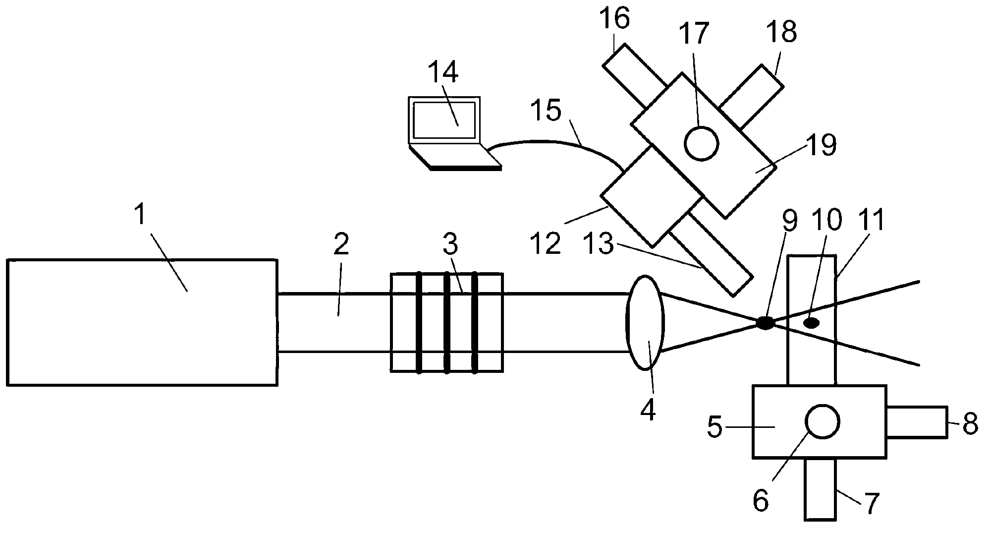
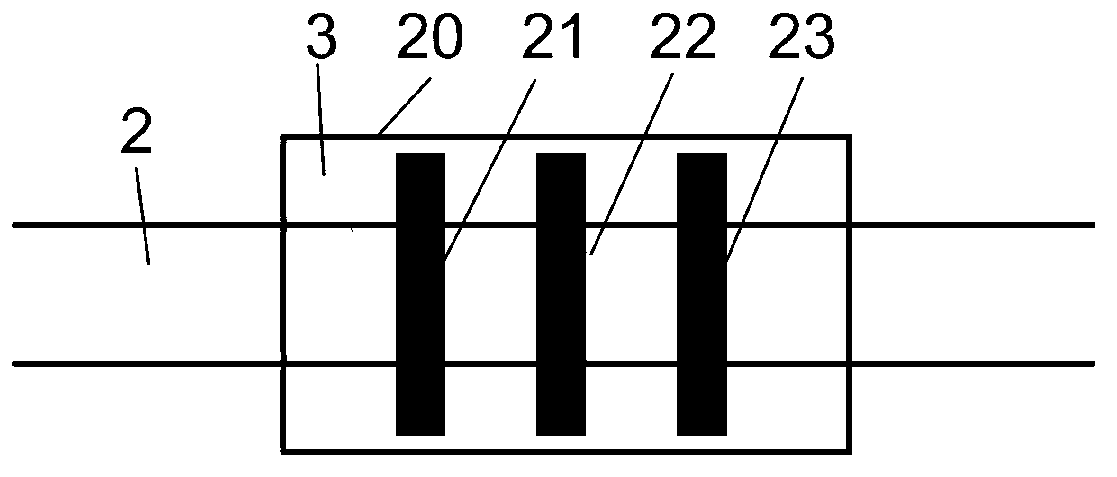
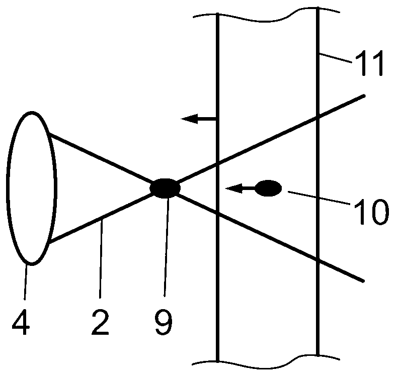
[0033] a kind of like figure 1 The laser focus positioning system of the present invention shown includes a laser device 1, an adjustable laser attenuation sheet system 3, a converging lens 4, a material translation device 5 and a CCD microscopic imaging system, and the laser beam 2 output by the laser device 1 passes through the laser attenuation sheet first The system 3 is parallel to the optical axis of the converging lens 4 and is vertically incident on the converging lens 4 . After being focused by the converging lens 4 , the output beam is incident on the surface of the optical material 11 to be measured or to be processed clamped on the material translation device 5 . The output wavelength of the laser 1 of the present embodiment is 800nm, the maximum output average power is 5W, and the beam quality factor M 2 is 1.2. The converging lens 4 of this embodiment is a short focal length focusing lens, and its focal length is 10 mm. Such as figure 2 As shown, the adjustab...


PUM

PropertyMeasurementUnit
lengthaaaaaaaaaa
diameteraaaaaaaaaa

Abstract

The invention discloses a system for laser focus positioning. The system for the laser focus positioning comprises a laser device, a convergent lens, a material translation device. A laser beam output from the laser device incidents on the convergent lens and incidents on the surface of an optical material which is clamped on the material translation device after focalized. A plasma body bright spot is produced after the laser beam is focalized and a bright spot mirror image is formed by the bright spot through the surface of the optical material. A charge coupled device (CCD) micro imaging system which is used for simultaneously collecting and outputting the images of the plasma body bright spot and the bright spot mirror image is further arranged. The invention further discloses a method for positioning the optical material on a laser focus point. The method includes that after focalized and output, the laser beam produces the plasma body bright spot by adjusting the laser device and the like, the surface of the material is controlled to approach the plasma body bright spot until the bright spot mirror image is formed, the plasma body bright spot and the bright spot mirror image are enabled to enter a view field of the CCD micro imaging system until a complete registration of the plasma body bright spot and the bright spot mirror image is achieved. The system for the laser focus positioning and the method for positioning the material on the laser focus point have the advantages of being convenient to operate, high in positioning precision and small in artificial factor intervention and the like.

Description

technical field [0001] The invention relates to a device and method for locating the material surface in the measurement of laser damage threshold on the surface of optical materials (or surface laser processing), in particular to a laser focus locating system and its locating method. Background technique [0002] The laser beam passes through the converging lens system to form the smallest spot size at the focal point and achieve the maximum power density. Using this feature, the focal point can be positioned. In the surface laser damage threshold measurement of optical materials such as optical window glass, film and crystal, positioning the material surface at the focal point can reduce the difficulty of damage. Also, in laser precision machining operations, the precise positioning of the material surface at the focal point enables the highest machining accuracy. [0003] Under the action of strong laser, materials such as optical window glass, film substrate and crystal...

Claims


Application Information

Patent Timeline
Patent Type & Authority Applications(China)
IPC IPC(8): B23K26/04B23K26/046G01N21/01
Inventor 朱志武程湘爱江天许中杰黄良金郑鑫邱伟成刘泽金
Owner NAT UNIV OF DEFENSE TECH
Why Eureka
Try Eureka