Device for locking a cover of an electrical switch

A technology of electrical switches and covers, which is applied in the field of cover devices, can solve problems such as strong mechanical pressure and damage, and achieve the effect of improving mechanical load capacity

Inactive Publication Date: 2013-03-20
SIEMENS AG
View PDF3 Cites 0 Cited by
  • Summary
  • Abstract
  • Description
  • Claims
  • Application Information

AI Technical Summary

Problems solved by technology

This high pressure can cause strong mechanical stress or possibly even damage to the accessory cover

Method used


Image

  • Device for locking a cover of an electrical switch
  • Device for locking a cover of an electrical switch
  • Device for locking a cover of an electrical switch

Examples


Embodiment Construction

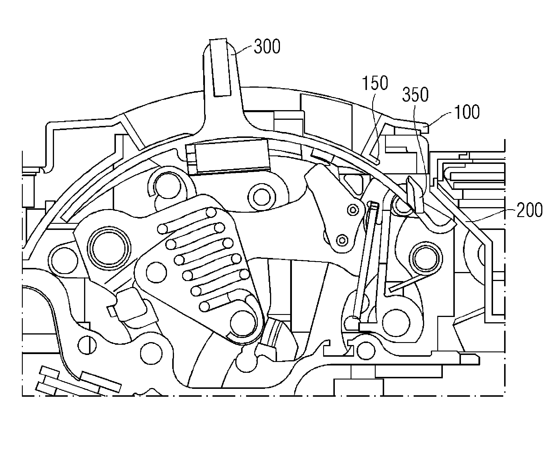
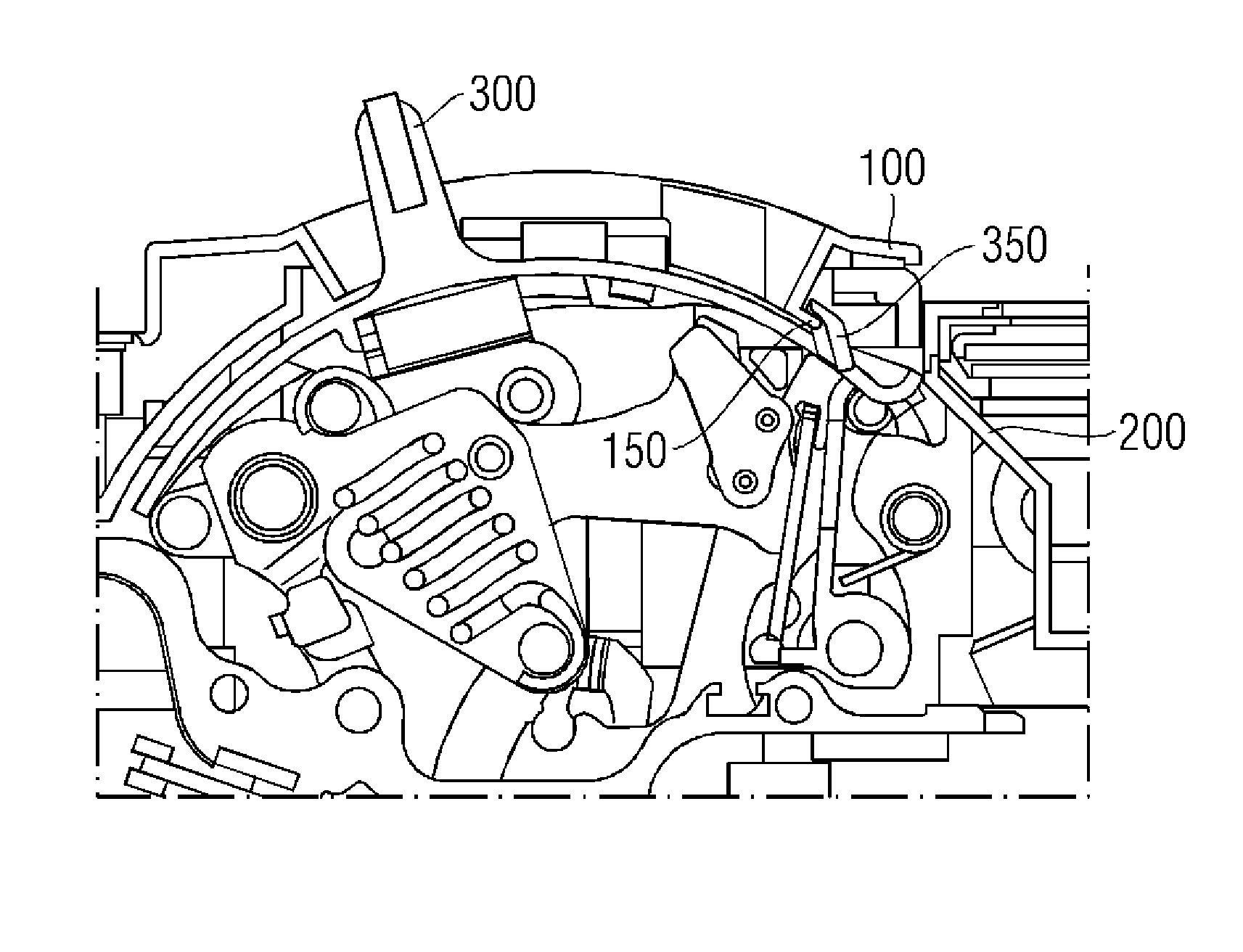
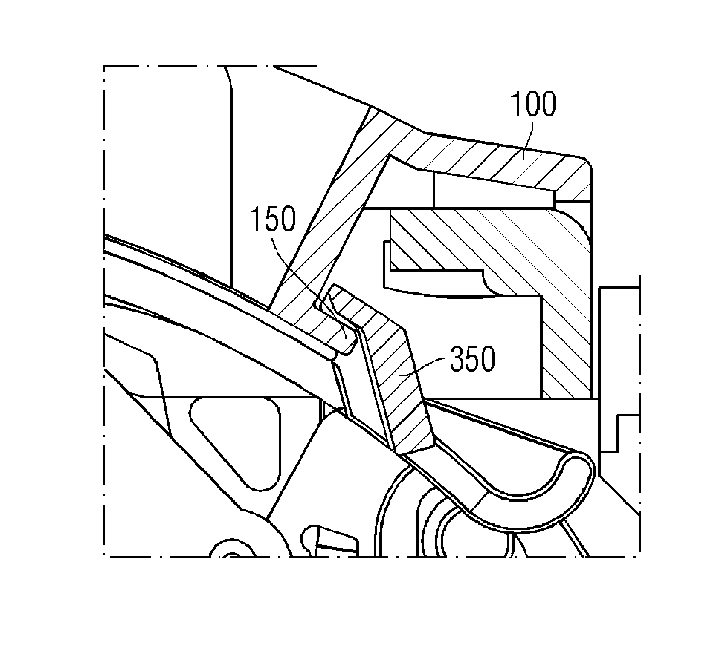
[0018] figure 1 A typical housing 200 of an electrical switch is shown. The housing 200 is provided with a removable cover 100 . The lid 100 includes an opening 230 through which the handle 300 protrudes after assembly.

[0019] The removable cover 100 should be designed in such a way that an assembler can easily remove it in order to gain access to the built-in accessories arranged under the removable cover 100 . For this, according to figure 1 , the removable cover 100 is provided with a hinge 210 on one side and screwed through a hole 220 on the other side. The removable cover 100 can thus be opened by unscrewing the screws in the screw holes 220 . Instead of hinge 210 , snap hooks, other suspension means or screw connections can also be provided. In the event that the electrical switch is short-circuited and cut off, the hinge 210 will not be able to bear the pressure and be damaged or destroyed. The device according to the invention also serves to increase the stabi...


PUM


Abstract

A device for locking a cover of an electrical switch. A device is disclosed including a removable cover of a housing of an electrical switch and a handle. In at least one embodiment, the handle, by way of its position, switches the electrical switch between different states. Further, the handle is connected to the housing and the handle includes a contour which is embodied, at least in one position of the handle, to interact with the cover for locking the removable cover.

Description

technical field [0001] The invention relates to a device for locking the cover of an electrical switch. Background technique [0002] Electrical switches are used to make and break electric current. One type of electrical switch is a so-called circuit breaker, which can usually make and break currents of 100A and above. Circuit breakers are usually mounted in housings. The individual phases of the current can be switched on and off in so-called pole boxes. For this purpose, the pole box includes a housing in which movable contacts and fixed contacts are accommodated, which can be connected or disconnected by mechanical separation or engagement. When the movable contact and the fixed contact of the pole box separate under the current, an electric arc is formed which is extinguished in the arc extinguishing chamber. The arc ionizes the gas in the arc chute and creates an overpressure in the arc chute corresponding to the energy of the arc. There are also known circuit bre...

Claims


Application Information

Patent Timeline
Patent Type & Authority Applications(China)
IPC IPC(8): H01H9/22
CPCH01H9/22H01H71/521H01H9/02H01H71/0228
Inventor J-U.达尔K.曼泰
Owner SIEMENS AG
Why Eureka
Try Eureka