Retainer and method for attaching lines to lightweight elements of means of transport, in particular to sandwich panels of aircraft

a technology of lightweight elements and retainers, which is applied in the direction of electrical equipment, building materials handling, construction, etc., can solve the problems of increased weight, danger of losing parts, and the fact that known retainers are only suitable to a limited extent for uncomplicated line attachment, and achieve the effect of fast and simple line attachmen

Inactive Publication Date: 2006-08-10
AIRBUS OPERATIONS GMBH
View PDF31 Cites 0 Cited by
  • Summary
  • Abstract
  • Description
  • Claims
  • Application Information

AI Technical Summary

Benefits of technology

[0008] Amongst other things, it may be an object of the invention to create a retainer and a method which make possible fast

Problems solved by technology

Accordingly, attaching such lines to lightweight elements by means of the known retainers always requires several work steps and is correspondingly involved.
Furthermore, the multitude of parts (insert, screw) required to attach the retaine

Method used


Image

  • Retainer and method for attaching lines to lightweight elements of means of transport, in particular to sandwich panels of aircraft
  • Retainer and method for attaching lines to lightweight elements of means of transport, in particular to sandwich panels of aircraft
  • Retainer and method for attaching lines to lightweight elements of means of transport, in particular to sandwich panels of aircraft

Examples


first embodiment

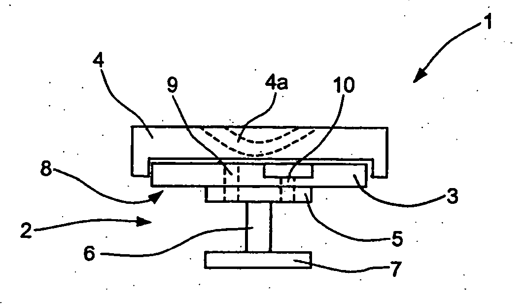
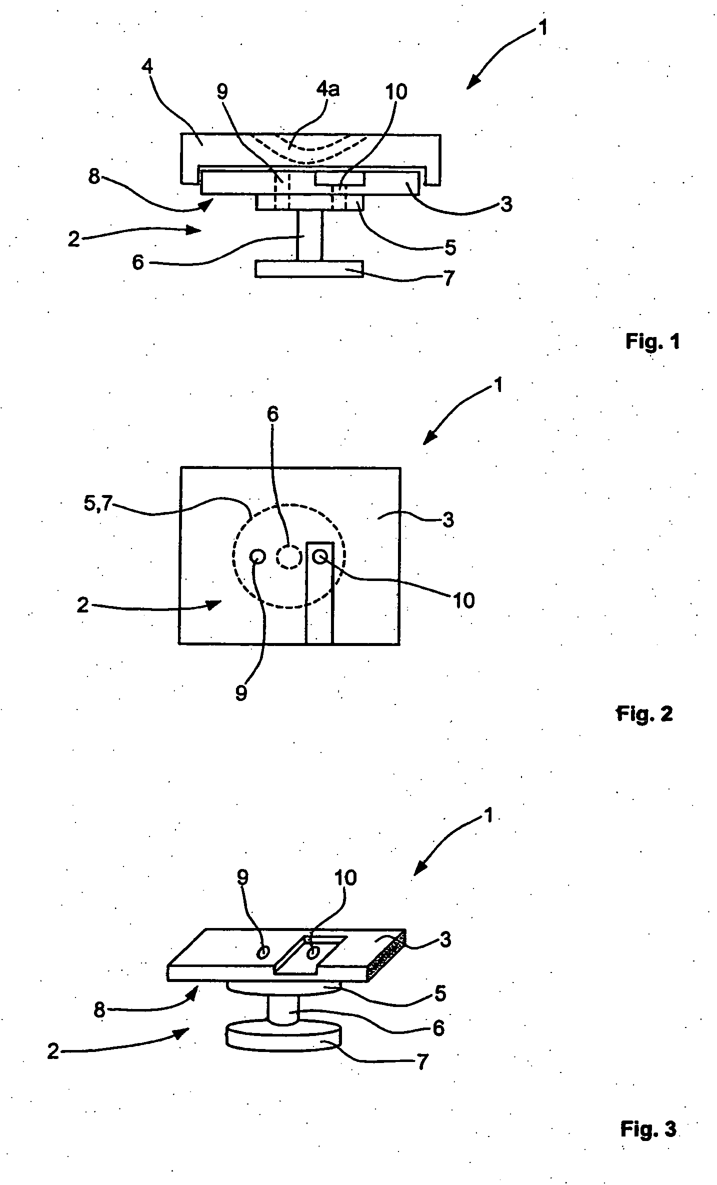
[0024]FIG. 1 shows a front view of a first embodiment variant of a holder 1 with a retaining stud 2.

[0025] The retaining stud 2 is arranged on a base plate 3. The base plate 3 and the retaining stud 2 are designed in one piece and together form the retainer 1. The retainer 1 can be made from a suitable material, for example in the injection moulding process, so as to reach through. Furthermore, the plastic material can also comprise fibre reinforcement.

[0026] An adapter 4 is attached to the base plate 3. Firm connection of the adapter 4 to the base plate 3 is by connection means (not shown in detail) such as for example snap-on elements or the like. In the adapter 4 a lead-through 4a for an attachment means, for example for a cable tie, is provided to attach one or several lines directly to the adapter 4.

[0027] In one embodiment variant of the adapter 4, said adapter 4 comprises accommodation means to connect to counterpieces located on the line. The accommodation means, the line ...

second embodiment

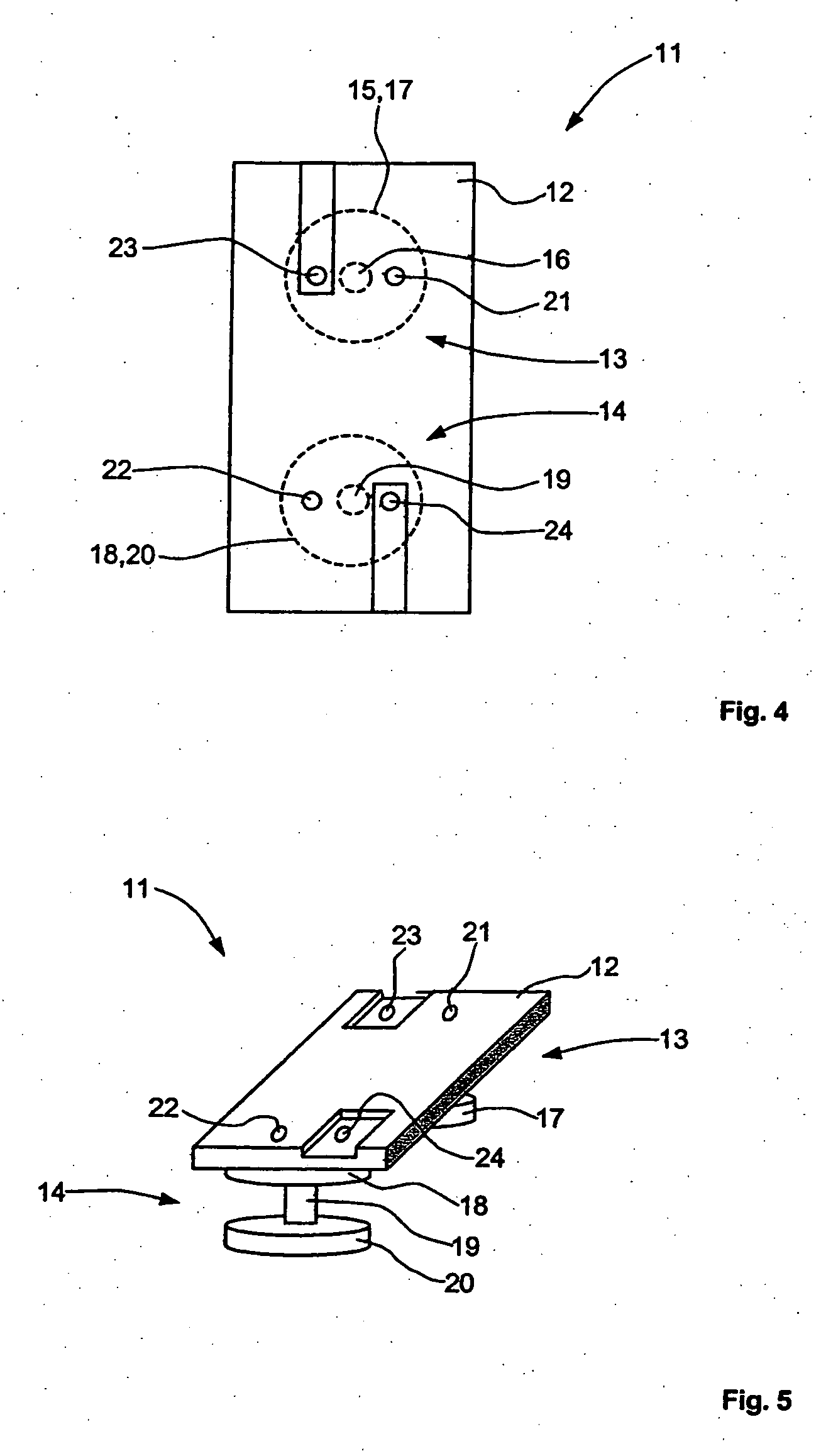
[0041]FIG. 4 shows a top view of a second embodiment variant of a retainer.

[0042] In a way that is different from the first embodiment variant of the retainer 1, the retainer 11 according to the second embodiment variant comprises a base plate 12 with two retaining studs 13, 14 so that rotation of the retainer 11 as a result of torsional forces is avoided.

[0043] Among other things the holder 11 comprises a base plate 12. Underneath the base plate 12 the two retaining studs 13, 14, which are covered up by the base plate 12, are arranged. The retaining stud 13 comprises an attachment section with a top section 15, a middle section 16 and an end section 17. Correspondingly, an attachment section of the retaining stud 14 comprises a top section 18, a middle section 19 and an end section 20. The retaining stud 13, 14 and the base plate 12 are designed in one piece; they can for example be made from a plastic material in an injection moulding process. As an alternative, the plastic mater...


PUM


Abstract

A retainer for attaching lines to lightweight elements of means of transport, in particular to sandwich panels of aircraft, with at least one base plate comprising at least one retaining stud. The retaining stud or studs can be cemented into a borehole within a lightweight element. The retaining studs are designed to be free of any undercut, and are connected in one piece to the base plate. A method is also provided for attaching lines to lightweight elements of means of transport, in particular to sandwich panels of aircraft, by means of a retainer comprising at least one retaining stud and a base plate.

Description

BACKGROUND OF THE INVENTION [0001] The invention relates to a retainer for attaching lines to lightweight elements of means of transport, in particular to sandwich panels of aircraft, with at least one base plate comprising a retaining stud. [0002] The invention relates to a retainer for attaching lines to lightweight elements of means of transport, in particular to sandwich panels of aircraft, with at least one base plate comprising a retaining stud. [0003] Furthermore, the invention relates to a method for attaching lines to lightweight elements of means of transport, in particular to sandwich panels of aircraft, by means of the retainer according to the invention. [0004] Known retainers for attaching lines in means of transport, in particular for attaching electrical, optical or hydraulic lines in aircraft, are generally optimised for use on structural elements. Such holders are normally attached directly to the respective aluminium or steel components, for example to stiffeners ...

Claims


Application Information

Patent Timeline
IPC IPC(8): E02D35/00
CPCH02G3/32
Inventor DIERGARDT, DANIEL
Owner AIRBUS OPERATIONS GMBH
Why Eureka
Try Eureka