Light reflector and barrier for light emitting diodes

a technology of light emitting diodes and reflectors, which is applied in the direction of circuit optical details, printed circuit non-printed electric components association, lighting and heating apparatus, etc. it can solve the problems of adjacent led's being bleed, producing indefinite indications for users, and the led's on the pcb being not directly visible by the user of the device, etc., to achieve quick and easy attachment

Inactive Publication Date: 2005-05-05
BROCADE COMMUNICATIONS SYSTEMS
View PDF8 Cites 30 Cited by
  • Summary
  • Abstract
  • Description
  • Claims
  • Application Information

AI Technical Summary

Benefits of technology

[0008] The light barrier may be fabricated by the injection molding of a thermoplastic resin and may optionally be equipped with snap-in type mounting studs for quick and easy attachment to a printed circuit board.

Problems solved by technology

However, since a PWB or PCB is typically mounted within a chassis of some sort, LED's on the PCB are usually not directly viewable by the user of the device.
However, there are a number of disadvantages associated with this system: the light pipes must be aligned with both the LED and the viewing lens or window; and, the light from adjacent LED's can “bleed over” into an adjoining light pipe producing indefinite indications to the user.
Moreover, light pipes are relatively costly and labor-intensive to install.

Method used


Image

  • Light reflector and barrier for light emitting diodes
  • Light reflector and barrier for light emitting diodes
  • Light reflector and barrier for light emitting diodes

Examples


Embodiment Construction

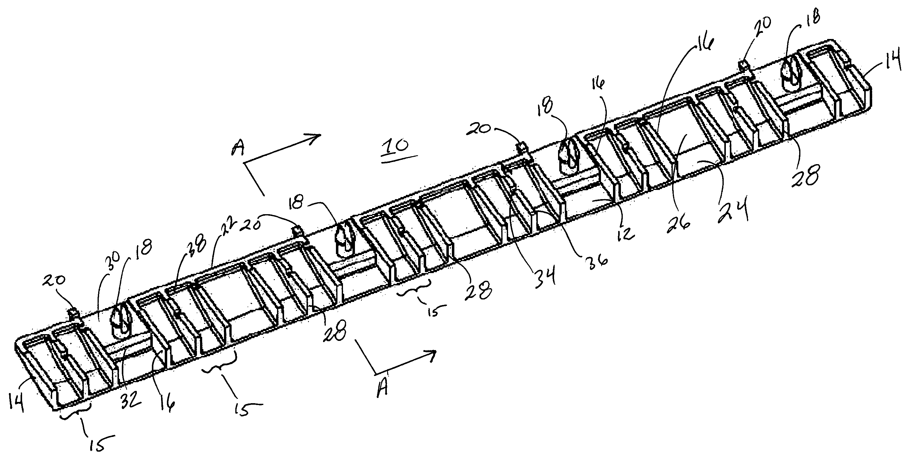
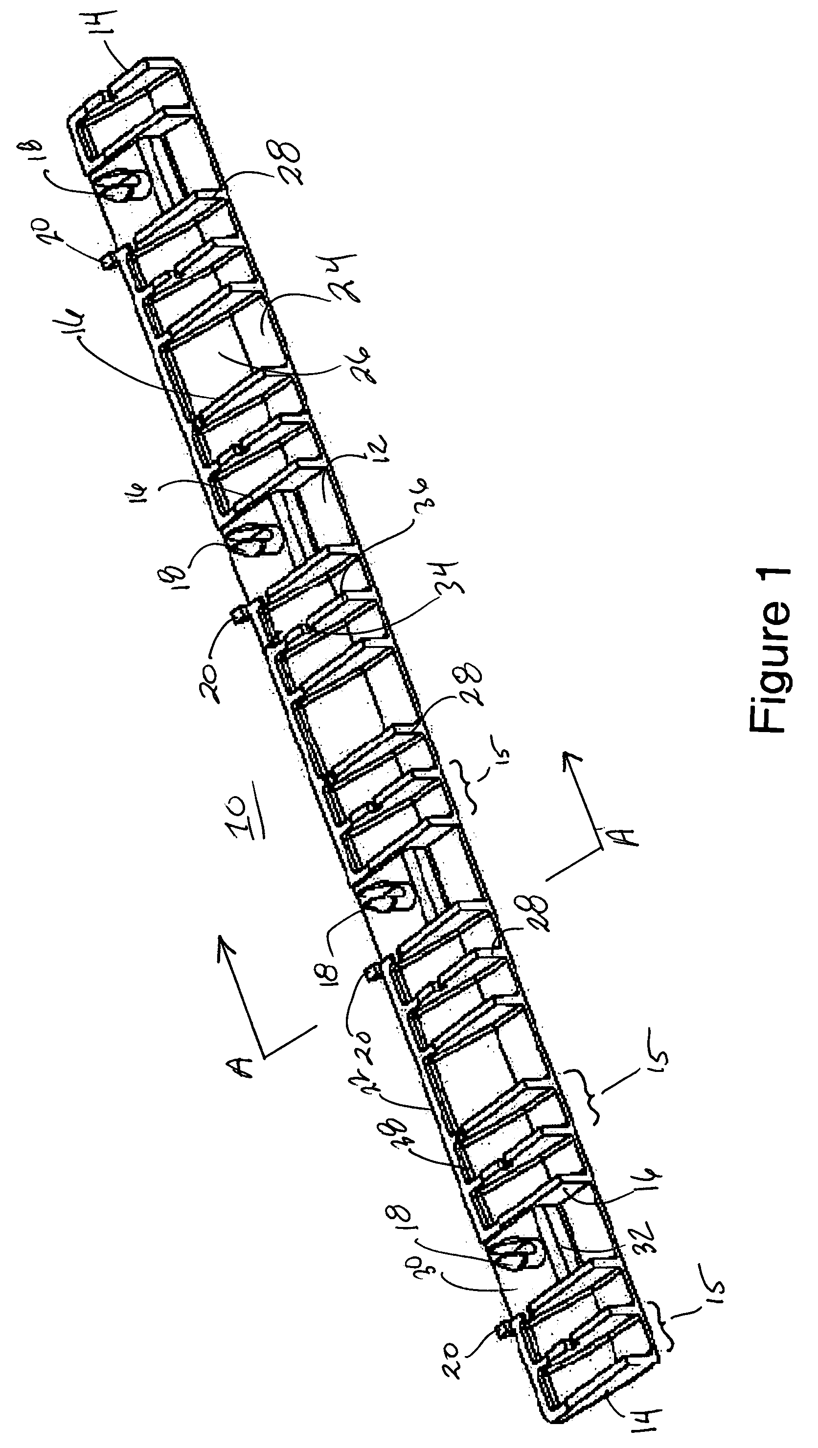
[0016]FIG. 1 illustrates in perspective view one particular embodiment of the invention which hereinafter may be referred to as a “light barrier” or a “light reflector” or a “barrier / reflector”. The light barrier 10 illustrated in FIG. 1 is adapted for mounting to a printed circuit board. The perspective view of FIG. 1 shows the surface which abuts the PCB and the front surface of the light barrier 10—i.e., the surface from which light is emitted. If the light barrier is mounted on the upper surface of a horizontal PCB, FIG. 1 may be considered a perspective view of the underside of light barrier 10 taken from the front side.

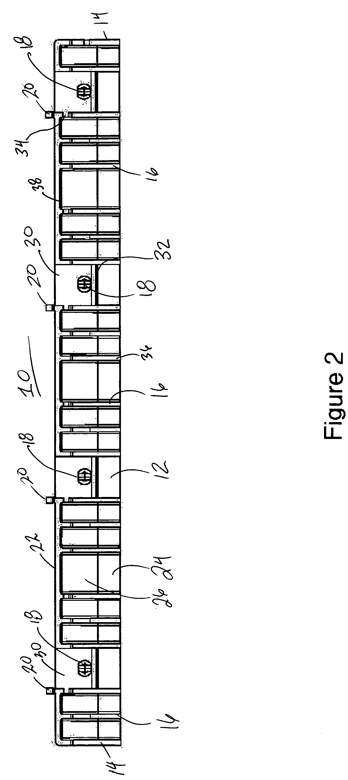
[0017] Light barrier 10 has segmented top 12 which comprise flat segment 24 and angled segment 26. End walls 14 connect top 12 to back wall 22. Interior walls 16 are attached to top 12 and back wall 22 to define compartments 15. Each compartment 15 is open on its bottom and front sides.

[0018] Interior walls 16 each comprise wall bottom 36 and wall front 28. Wa...


PUM


Abstract

A light barrier and / or light reflector for PCB-mounted LED's has reflective walls defining interior chambers which redirect the light from the LED's in a substantially orthogonal direction and shield each LED from the light emitted by adjacent LED's. The device is particularly suited for redirecting light from LED's on a PCB to a status indicator panel thereby replacing conventional light pipes.

Description

BACKGROUND [0001] 1. Field of the Invention [0002] This invention relates to light barriers or shields. More particularly, it relates to devices for directing and shielding the light from light emitting diodes (LED's) that are mounted on printed circuit boards (PCB's). [0003] 2. Description of the Related Art [0004] LED's are particularly suited for use as status indicators for various electronic circuits and systems. They are small, relatively inexpensive, have modest power requirements, produce little heat and have a long working life. LED's are available from a variety of sources in packages which permit direct mounting to a printed wiring board (PWB). However, since a PWB or PCB is typically mounted within a chassis of some sort, LED's on the PCB are usually not directly viewable by the user of the device. [0005] In the past, light pipes comprised of rods or bundles of fibers of clear plastic or glass have been used to direct the light from PCB-mounted LED's to lenses or windows...

Claims


Application Information

Patent Timeline
Patent Type & Authority Applications(United States)
IPC IPC(8): H05K1/02H05K1/18
CPCH05K1/0274H05K2201/2054H05K2201/10106H05K1/18
Inventor MOONEY, DOUGLAS J.
Owner BROCADE COMMUNICATIONS SYSTEMS
Why Eureka
Try Eureka