Self-adjusting snow plow

a self-adjusting, snow plow technology, applied in snow cleaning, way cleaning, construction, etc., can solve the problems of individuals purchasing and using such vehicles, affecting the use of pedestrian and vehicular travel surfaces, and removing snow from open ground, etc., to achieve easy drawing of the plow blades and simple installation

Inactive Publication Date: 2005-03-31
AGRI COVER
View PDF99 Cites 33 Cited by
  • Summary
  • Abstract
  • Description
  • Claims
  • Application Information

AI Technical Summary

Benefits of technology

[0010] It is a further objective of the present invention to provide such an apparatus for snow removal that is much simpler to install and use then other similar devices commonly found in the market today.
[0011] It is a further objective of the present invention to provide such an apparatus for snow removal which includes a plow blade which is relatively light and allows an individual person to lift respective ends of the plow blade in order to lower them into position for clearing snow or to lift the respective ends of the plow blade to secure the blade in position for transit.
[0012] It is a further objective of the present invention to provide such an apparatus for snow removal that does not require the owner of the vehicle to purchase separate running lights for the vehicle in order to use the self-adjusting snow plow.
[0013] It is yet another objective of the present invention to provide such an apparatus for snow removal that easily slid

Problems solved by technology

Moving snow off of open ground, streets, sidewalks and parking lots is an age-old problem in less temperate climates where significant snowfall is anticipated during colder periods of the year.
If the snow is allowed to accumulate over a period of weeks, the snow eventually makes the use of these surfaces for pedestrian and vehicular travel difficult, if not treacherous.
However, the purchase and use of such a vehicle by individuals, who have a need to move accumulated snow in smaller areas, is less feasible.
First of all, the larger vehicles are expensive to purchase and maintain and are, in some case

Method used


Image

  • Self-adjusting snow plow
  • Self-adjusting snow plow
  • Self-adjusting snow plow

Examples


Embodiment Construction

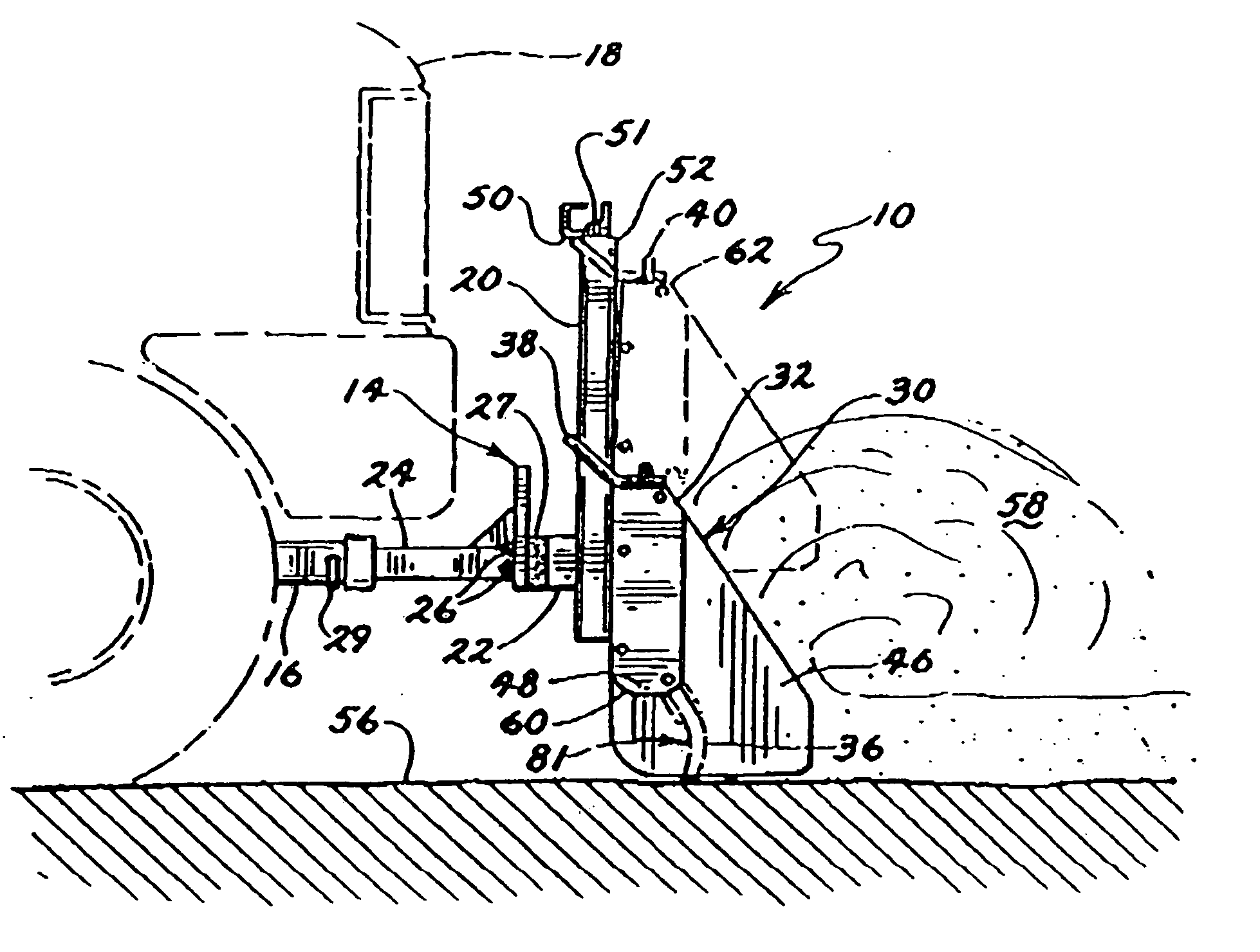
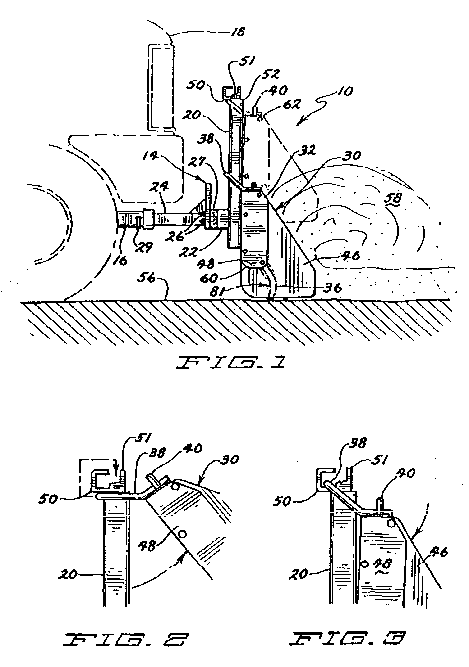
[0042] Referring now to the drawings, and more particularly FIGS. 1-3, a preferred self-adjusting snow plow 10 of the present invention is shown. The preferred snow plow 10 includes a mounting apparatus 14 and a plow blade 30. Referring now also to FIGS. 7 and 8, the preferred mounting apparatus 14 includes a hitch receiver 16 which is secured to a vehicle 18 (partially shown in phantom in FIG. 1). The mounting apparatus 14 also includes two mounting uprights 20 that are interconnected by an interconnecting member 22. In this embodiment, a hitch tongue 24 is secured to the interconnecting member 22 by a series of bolts 25 secured by nuts 26. The bolts 25 secure the hitch tongue 24 to the interconnecting member 22 with a resilient rubber connecting member 27 interspersed between the interconnecting member 22 and a flat connecting plate 28 of the hitch tongue 24. A securing pin 29 secures the hitch tongue in the hitch receiver 16. The resilient rubber connecting member 27 allows the e...


PUM


Abstract

A self-adjusting snow plow for use with pickup trucks and sport utility vehicles is disclosed. The snow plow includes a mounting apparatus for attachment to a vehicle and a plow blade having first and second ends, a top, a bottom, a plurality of retention members and a rubber scraper. The mounting apparatus includes a pair of mounting uprights and a hitch tongue which is easily mounted in a hitch receiver which is secured to the front of a vehicle. The retention members are constructed and arranged to at least partially encircle and slideably engage one of the respective mounting uprights and the retention members allow the respective ends of the plow blade to slide upward relative to the mounting upright most proximate to that end of the plow while the other end of the plow remains generally in the same position relative to the mounting upright proximate that end of the plow blade. The retention members also permit the bottom of the plow blade to pivot away from the respective mounting uprights when the plow blade is engaged with the mounting apparatus in a working orientation and the vehicle is in motion in a direction rearward of the plow blade.

Description

RELATED APPLICATIONS [0001] The present application is related to and claims priority to U.S. patent application Ser. No. 10 / 841,740, filed May 7, 2004 and U.S. patent application Ser. No. 10 / 404,164, filed Mar. 31, 2003, (issuing Nov. 16, 2004, as U.S. Pat. No. 6,817,118) both entitled Self-Adjusting Snow Plow, both of which claim priority to PCT application No. PCT / US01 / 47125 for SELF-ADJUSTING SNOW PLOW, filed Nov. 12, 2001, and each of which are hereby incorporated by reference.FIELD OF THE INVENTION [0002] The present invention relates to adjustable snow plows for attachment to personal utility vehicles such as pickup trucks and sport utility vehicles. BACKGROUND OF THE INVENTION [0003] Moving snow off of open ground, streets, sidewalks and parking lots is an age-old problem in less temperate climates where significant snowfall is anticipated during colder periods of the year. For instance, in many parts of Canada and in many northern states in the United States, significant sn...

Claims


Application Information

Patent Timeline
IPC IPC(8): E01H5/06
CPCE01H5/061E01H5/06
Inventor SCHMEICHEL, CHARLES M.
Owner AGRI COVER
Why Eureka
Try Eureka