Rotor Support and Method for Producing a Rotor Support

a technology of rotor support and rotor body, which is applied in the direction of magnetic circuit rotating parts, magnetic circuit shape/form/construction, mechanical energy handling, etc., can solve the problems of considerable fluctuation of the performance of individual electrical machines manufactured in series, and affecting the performance of individual electrical machines. , to achieve the effect of improving the strength and mechanical capacity of the support pot, high precision and integral manner

Inactive Publication Date: 2015-04-30
DAIMLER AG
View PDF9 Cites 0 Cited by
  • Summary
  • Abstract
  • Description
  • Claims
  • Application Information

AI Technical Summary

Benefits of technology

[0030]The method comprises the production of a preliminary shape of a support pot having a hub, wherein the preliminary shape is produced by flow forming (flow forming method) from a blank. For flow forming, an end stop is produced for a supporting element, with the end stop being formed by flow forming. The end stop is preferably formed in the region of a flange-like, preferably conical extension of a peripheral wall of the support pot. A flow forming method provides a very sophisticated means to form the support pot of a rotor arm with narrow tolerances, in a highly precise and integral manner. Likewise, it is readily possible to form the end stop for the supporting element on the inner peripheral surface of the support pot directly during flow forming, in an axial direction from the hub. No further method steps are required here. In particular, with the aid of flow forming, it is possible to form the preliminary shape of the support pot in such a way that it already substantially corresponds to a final shape. Subsequent processing steps that are necessary to ensure functionality and adherence to the tolerance requirements regarding the rotor arm described above, in particular cutting finishing, are shortened by this, and very little material must be removed in order to arrive at the final shape from the preliminary shape. On the one hand, this saves material and on the other hand improves the strength and the mechanical capacity of the support pot, because a fiber flow in this is only slightly disturbed by the cutting method if very little material is removed. It is therefore possible to guarantee or improve the local basic strength and/or the total strength and thus the mechanical capacity of the support pot. Moreover, particularly low tolerances can be produced in this way, so that, on the whole, the advantages described above in relation to the rotor arm can be achieved.
[0031]A method is preferred that is characterized in that the blank is produced using solid forming, preferably as a forged part, preferably by means of drop forging. If a forging process, forging or a forged part is referred to in the following, this

Problems solved by technology

Small variations in a predetermined clearance between the rotor and stator, which may even vary along the periphery, can lead to considerable performance losses of 30% or more of the power rating of the electrical machine.
Imbalances also lead to corresponding performance losses.
In particular, tolerances and imbalances due to tolerance also lead to considerable fluctuation of the performance of individual electrical machines manufactured in series, viewed across the entire series.
This generally leads either to only a low mechanical capacity of the rotor arm, if this is formed with thin walls and is correspondingly light, or it leads to rotor arm that is formed with comparatively thick walls and is heavy, if this is formed with a high mechanical load capacity.
It is therefor

Method used


Image

  • Rotor Support and Method for Producing a Rotor Support
  • Rotor Support and Method for Producing a Rotor Support
  • Rotor Support and Method for Producing a Rotor Support

Examples


Embodiment Construction

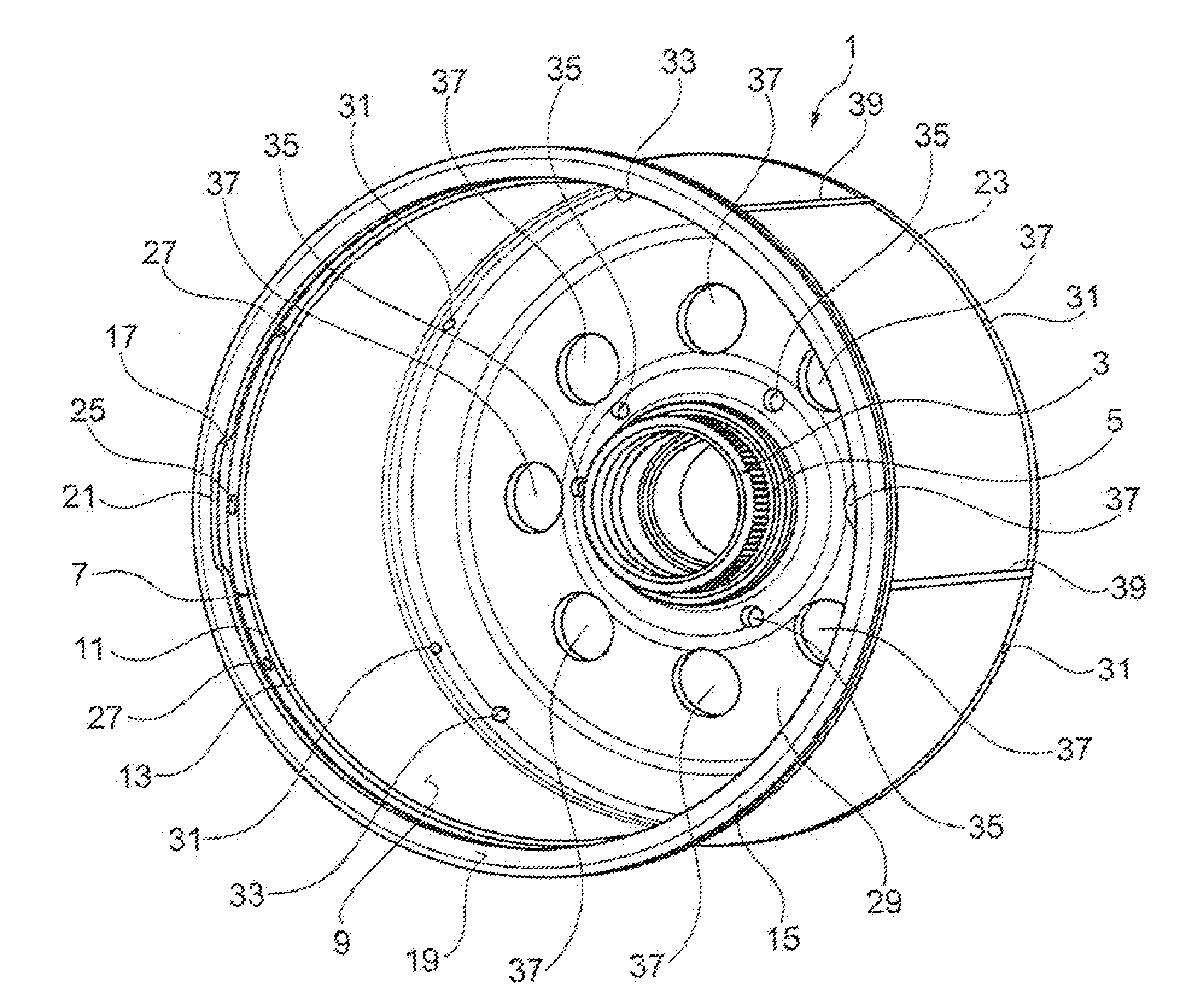
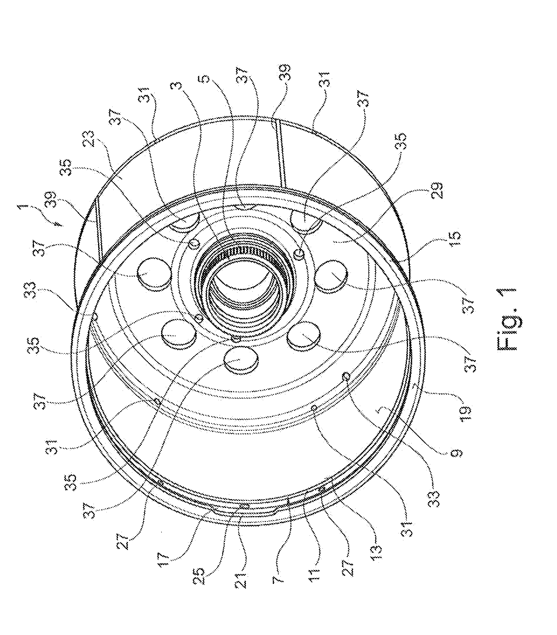
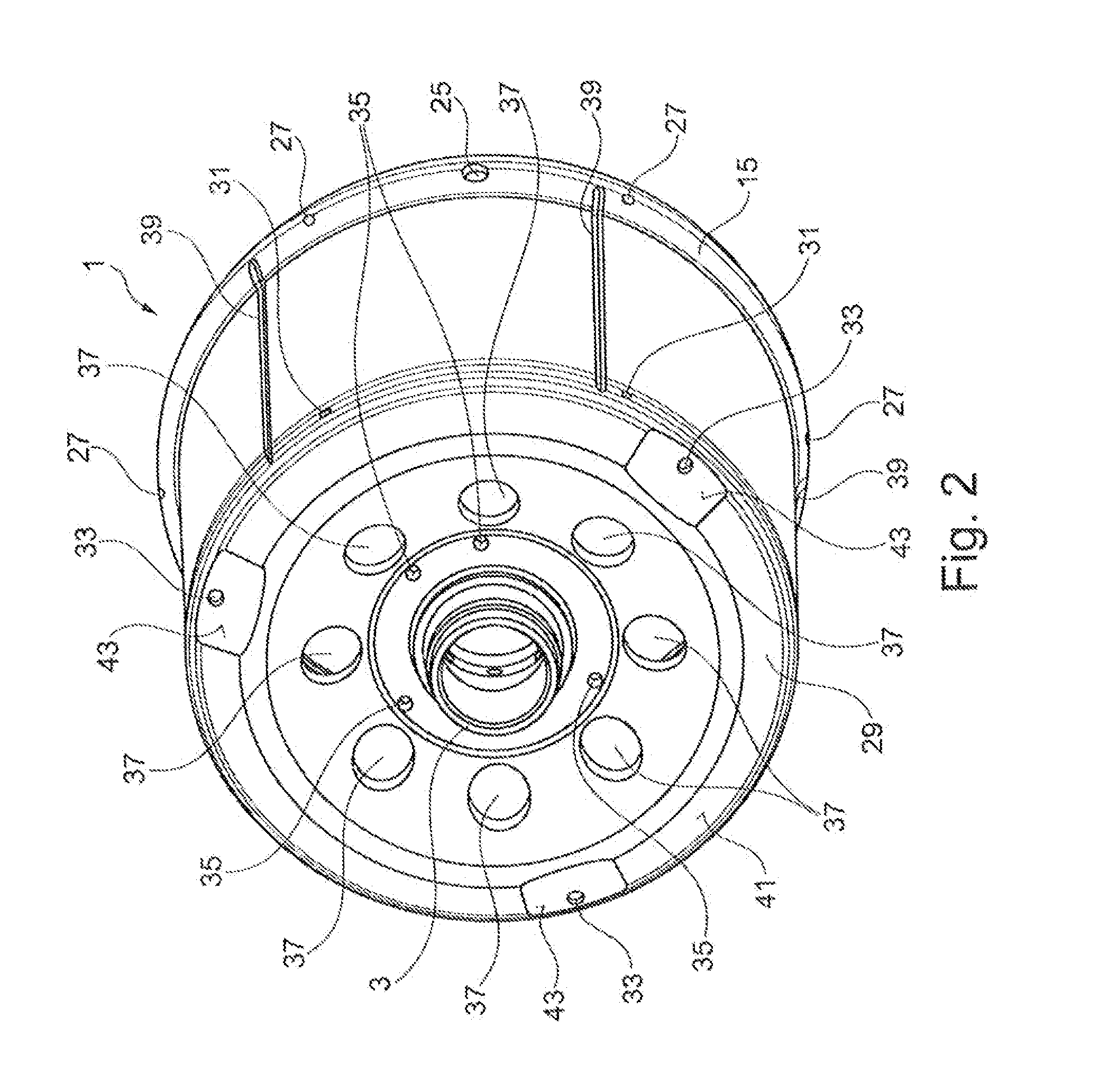
[0041]FIG. 1 shows a three-dimensional view of an exemplary embodiment of a support pot 1, wherein its interior is facing the observer. It has a hub 3 to bear a drive shaft which is not shown, wherein a roller or needle bearing is pressed into the hub 3 in the assembled state, with which the drive shaft is connected rotatably with the support pot 1. The drive shaft is preferably mounted axially and / or radially in the hub 3.

[0042]The hub 3 has a retainer 5 for a clutch on its outer peripheral surface, which is formed here as a plug-in toothing connection. In the assembled state, a multiple disc clutch is preferably attached to the plug-in toothing connection 5 with a corresponding internal toothing system. In the process, the clutch non-rotatable couples the support pot 1 with the drive shaft.

[0043]An end stop 7 is provided on an end of the support pot 1 that is turned away from the hub 3, which is formed here as a recess of an inner peripheral surface 9 of the support pot 1. In the ...


PUM

PropertyMeasurementUnit
Thicknessaaaaaaaaaa
Shapeaaaaaaaaaa
Distanceaaaaaaaaaa

Abstract

A rotor arm for an electrical machine includes a support pot for mounting a magnetic element. The support pot has a hub bearing a drive shaft. An inner peripheral surface of the rotor arm has, in an axial direction from the hub, an end stop for a supporting element of the rotor arm for the further bearing of the drive shaft.

Description

BACKGROUND AND SUMMARY OF THE INVENTION[0001]Exemplary embodiments of the invention relate to a rotor arm for an electrical machine and a method for the production of a rotor arm.[0002]Rotor arms for electrical machines and methods for their production are known. An electrical machine has a stator and a rotor, mounted for rotation within it, wherein an electromagnetic coupling between the rotor and stator can be produced, which ensures that either electrical energy supplied to electrical machine is converted into mechanical energy, or that mechanical energy supplied to the electrical machine is converted into electrical energy. The electrical machine therefore operates either as a motor or as a generator. In the process, it is possible that the same electrical machine, depending on the operating type, is used as a motor and as a generator. For example, this is known from the automobile sector, where it is possible, particularly in the field of hybrid vehicles or purely electrically ...

Claims


Application Information

Patent Timeline
IPC IPC(8): H02K1/27H02K15/14
CPCH02K15/14H02K1/2786H02K1/30H02K7/088H02K5/1737H02K15/03Y10T29/49009H02K1/2791
Inventor DOERINGER, MARTINKEMPF, MANFREDMERHEIM, HANS-GUENTHER
Owner DAIMLER AG
Why Eureka
Try Eureka