Centrifugal pressure plate automatic clutch

An automatic clutch and centrifugal technology, applied in the direction of automatic clutches, clutches, mechanical equipment, etc., can solve the problems of cost increase, unsuitable application, energy consumption, etc., and achieve the effects of easy manufacturing or transformation, favorable promotion and implementation, and reasonable structure

Inactive Publication Date: 2015-07-15
杨勇
View PDF5 Cites 0 Cited by
  • Summary
  • Abstract
  • Description
  • Claims
  • Application Information

AI Technical Summary

Problems solved by technology

[0003] However, the centrifugal clutch also has its own disadvantages: 1) The engagement of the clutch depends on the centrifugal force, so it cannot transmit a load greater than the rated torque
2) Since the centrifugal clutch force is proportional to the square of the rotational speed, and the output power changes with the cube of the operating rotational speed, it is not suitable for use in variable speed transmission systems
Centrifugal clutches should not be used on low-speed shafts. In order to achieve sufficient centrifugal force at low speeds, the structural size must be increased, which will increase the cost.
3) When the prime mover does not reach the rated speed, the centrifugal body will slip relative to the driven part, which will generate frictional heat and consume part of the energy. long place application

Method used


Image

  • Centrifugal pressure plate automatic clutch
  • Centrifugal pressure plate automatic clutch

Examples


Embodiment 1

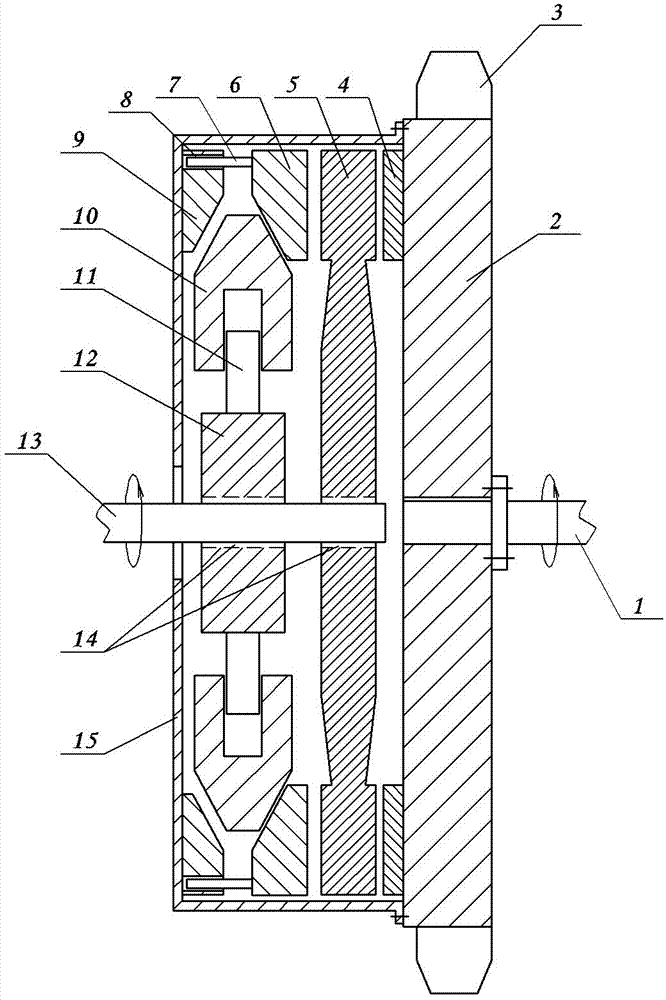
[0015] Embodiment 1: see figure 1 , the first centrifugal pressure plate automatic clutch, including the pressure plate 15, the driving part 12, the centrifugal body 10 and the driven part 2 and so on. The rotating shaft 13 of the driving part is connected to the rotating shaft of the power machine (such as an engine), and the driven part 2 is connected to the load through transmission. The driven part 2 can be connected to the load directly or through mechanisms such as pulleys. figure 1 The load in is the flywheel 3 integrated with the follower 2. A radial guide structure is set between the centrifugal body 10 and the active part 12, the specific structure is as figure 1 As mentioned above, a radial guide rod 11 is provided on the active member 12, and a corresponding radial guide groove is provided on the centrifuge body 10, and the two are matched and installed. In addition, a friction disc 5 is provided, and the friction disc 5 is installed on the rotating shaft 13 of t...

Embodiment 2

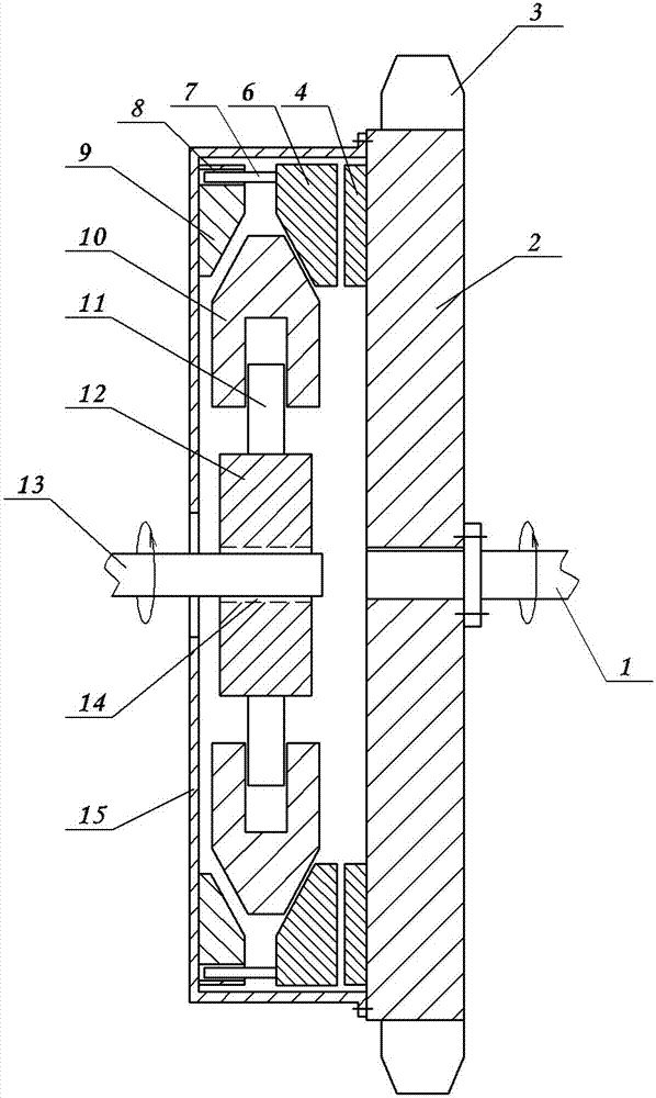
[0016] Example 2: see figure 2 , the second centrifugal pressure plate automatic clutch, including a pressure plate 15, a driving part 12, a centrifugal body 10 and a driven part 2, the rotating shaft 13 of the driving part is connected with the rotating shaft of the power machine, the driven part 2 is connected with the load transmission, and the driven part Part 2 is connected to the load transmission, and the driven part 2 can be connected to the load directly or through mechanisms such as pulleys. figure 2 The load in is the flywheel integrated with the follower. A radial guide structure is set between the centrifugal body 10 and the active part 12, the specific structure is as figure 2 As mentioned above, a radial guide rod 11 is provided on the active member 12, and a corresponding radial guide groove is provided on the centrifuge body 10, and the two are matched and installed. The driving member 12 is splined to the rotating shaft 13 of the driving member. The pre...


PUM


Abstract

The invention discloses a centrifugal pressure plate automatic clutch which comprises a pressure plate, a driving part, a centrifugation body and a driven part. A fixed block and a sliding block are arranged in the pressure plate. A cone-shaped opening is formed in the inner edges of the fixed block and the sliding block. The outer edge of the centrifugation body is arranged to be a cone-shaped protrusion. The cone-shaped protrusion and the cone-shaped opening can be arranged together in a matching mode. One side, close to the driven part, of the sliding block is matched with the driven part in a mode of friction through a friction disc or is directly matched with the driven part in the mode of friction. According to the centrifugal pressure plate automatic clutch, radial pressure of the centrifugation body is converted to axial pressure, pressure of a friction surface is enabled not to be changed easily, load with large torque can be transmitted, influence of speed changing is almost avoided, and the problem of friction heating before reaching rated rotating speed is almost not considered. The centrifugal pressure plate automatic clutch is reasonable in structure, and good in using effect, and can be popularized and implemented conveniently.

Description

technical field [0001] The invention relates to the improvement technology of a motor vehicle clutch, in particular to a centrifugal pressure plate automatic clutch. Background technique [0002] The centrifugal clutch transmits torque through friction. When the driving part reaches the specified angular velocity, the centrifugal body is thrown out and pressed against the inner wall of the driven part, and is forced into motion by friction to transmit torque. Because the centrifugal force gradually increases with the increase of the speed, the use of the centrifugal clutch is equivalent to gradually adding the load to the prime mover, so that the working machine can be started directly, and the effect of smooth starting can be obtained. If the centrifugal clutch and the motor are directly connected drive, can significantly reduce the start-up current. Centrifugal clutches have some characteristics that other clutches do not have, so they are widely used in industry. [00...

Claims


Application Information

Patent Timeline
Patent Type & Authority Patents(China)
IPC IPC(8): F16D43/18
Inventor 杨勇
Owner 杨勇
Why Eureka
Try Eureka