Piezoelectric micro-mixer

A micro-mixer and piezoelectric technology, applied in the field of micro-mechanics, can solve the problems of shortened mixing time, poor controllability, poor mixing effect, etc.

Inactive Publication Date: 2013-06-26
JIANGSU UNIV
View PDF6 Cites 13 Cited by
  • Summary
  • Abstract
  • Description
  • Claims
  • Application Information

AI Technical Summary

Problems solved by technology

There are also channel structures such as C-type, Z-type, curved arc pipe, L-type, T-type, modified tesla structure, twisted pipe and other channel structures by bending the channel in a spatial range. The active micro-mixer is divided according to the principle of action. It can be divided into electrodynamic type, magnetic dynamic type, ultrasonic type, branch injection type, piezoelectric type, magnetic induction type, jet type, mechanical type, etc.; for example, the vibration source of the ultrasonic brake micro-mixer studied by Yang et al. Electroceramics (PZT), Frédéric Bottausci's group developed a spider micro-mixer, etc. Passive micro-mixers do not requir

Method used


Image

  • Piezoelectric micro-mixer
  • Piezoelectric micro-mixer
  • Piezoelectric micro-mixer

Examples


Embodiment Construction

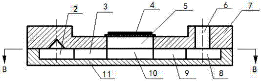
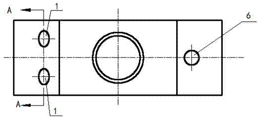
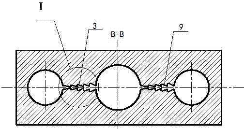
[0022] Such as figure 1 , figure 2 , image 3 and Figure 4 As shown, the present invention includes two pump inlet passages 1, an inlet buffer chamber 2, an inlet scroll tube 3, a piezoelectric vibrator 4, an upper base body 7, a pump body 11, a pump chamber (the base pump chamber 5 and the pump body pump chamber 10 ), an outlet vortex tube 9, an outlet buffer chamber 8 and a pump outlet channel 6; the upper substrate 7 and the piezoelectric vibrator 4, the pump body 11 and the upper substrate 7 are combined by anodic bonds and processes, and the upper substrate 7 has two pumps Inlet channel 1, substrate pump cavity 5 and a pump outlet channel 6; the structure of the piezoelectric vibrator is as follows image 3 As shown, the piezoelectric ceramics are bonded on the elastic substrate (brass material) through an adhesive (conductive epoxy resin), and there is a very thin electrode layer on the piezoelectric ceramics, and the piezoelectric vibrator 4 is a circular composite...


PUM


Abstract

The invention relates to the field of micro-mechanics for microfluid pumping and mixing, and in particular relates to a piezoelectric valveless micro-mixer, which comprises two inlet channels, an inlet buffer chamber, an inlet vortex tube, pump chambers, a piezoelectric vibrator, an upper substrate, a pump body, an outlet vortex tube, an outlet buffer chamber and an outlet channel. The two inlet channels are intersected at the inlet buffer chamber, the included angle of central lines of the two inlet channels is less than or equal to 90 degrees, and the vortex tubes are produced by adding triangular bodies in diffusion tubes. The piezoelectric micro-mixer provided by the invention has the main advantages that the two inlet channels are intersected at the inlet buffer chamber, so that fluids to be mixed are firstly mixed in the inlet buffer chamber, and then are further mixed in the specially designed vortex tubes effectively, so that the required mixing time is greatly shortened, and the mixing efficiency is improved.

Description

technical field [0001] The invention relates to the micromechanical field of microfluid pumping and mixing, in particular to a piezoelectric valveless micromixer. Background technique [0002] Microfluidic chip is an important branch of MEMS research, which can realize the separation, addition, mixing, reaction, detection and other functions of traditional biochemical detection process on the chip. Microfluidic chip can realize fluid flow from nanoliter to microliter The control and drive of the microfluidic chip can realize the precise control of the flow of a small amount of liquid, and has been widely used in many fields such as chemical analysis, disease diagnosis, drug screening, etc.; and the micromixer is one of the important functional devices in the microfluidic chip. The ratio of the surface area to the volume of the fluid in the microchannel is quite large, the flow velocity and Reynolds number of the liquid are low, and it is often in a state of laminar flow, wh...

Claims


Application Information

Patent Timeline
IPC IPC(8): B01F5/00B01F5/12F04B43/04B01F25/60
Inventor 何秀华邓志丹韦丹丹蔡盛川禚洪彩
Owner JIANGSU UNIV
Why Eureka
Try Eureka