Low-pollution combustion chamber adopting fuel-grading and three-stage cyclone air inlet

A combustor, low-pollution technology, applied in the direction of combustion chamber, continuous combustion chamber, combustion method, etc., can solve the problem of increasing the complexity of the fuel and air mixing device at the head of the combustion chamber, poor fuel atomization effect in the duty area, CO and Increased UHC emissions and other issues to achieve the effect of broadening the stable working range, suppressing the formation of local hot spots, and increasing the intake air volume

Active Publication Date: 2013-08-21
中科航空动力(株洲)装备制造研究院有限公司
View PDF16 Cites 45 Cited by
  • Summary
  • Abstract
  • Description
  • Claims
  • Application Information

AI Technical Summary

Problems solved by technology

China's Beijing University of Aeronautics and Astronautics has also applied for a number of patents on low-pollution combustors. Patent application number: 200710178394. input, there is also the problem of short blending length
Patent application number: 201010101574.X Proposed low-pollution combustor with pre-mixed pre-evaporation ring. The main combustion grade fuel is supplied in a tangential or axial manner, which increases the complexity of the fuel and air mixing device at the head of the combustor.
200810105062.3 proposed a premixed pre-evaporation combustor in which the main combustion stage is directly injected in the turning area of ​​the radial swirler, but the duty class only has a first-stage swirler, and the atomization effect of the fuel in the duty area is not good, which is not conducive to the duty class flame stabilization
But on the other hand, if the combustion temperature is too low, it will cause insufficient fuel combustion, which will increase the emission of CO and UHC

Method used


Image

  • Low-pollution combustion chamber adopting fuel-grading and three-stage cyclone air inlet
  • Low-pollution combustion chamber adopting fuel-grading and three-stage cyclone air inlet
  • Low-pollution combustion chamber adopting fuel-grading and three-stage cyclone air inlet

Examples


Embodiment Construction

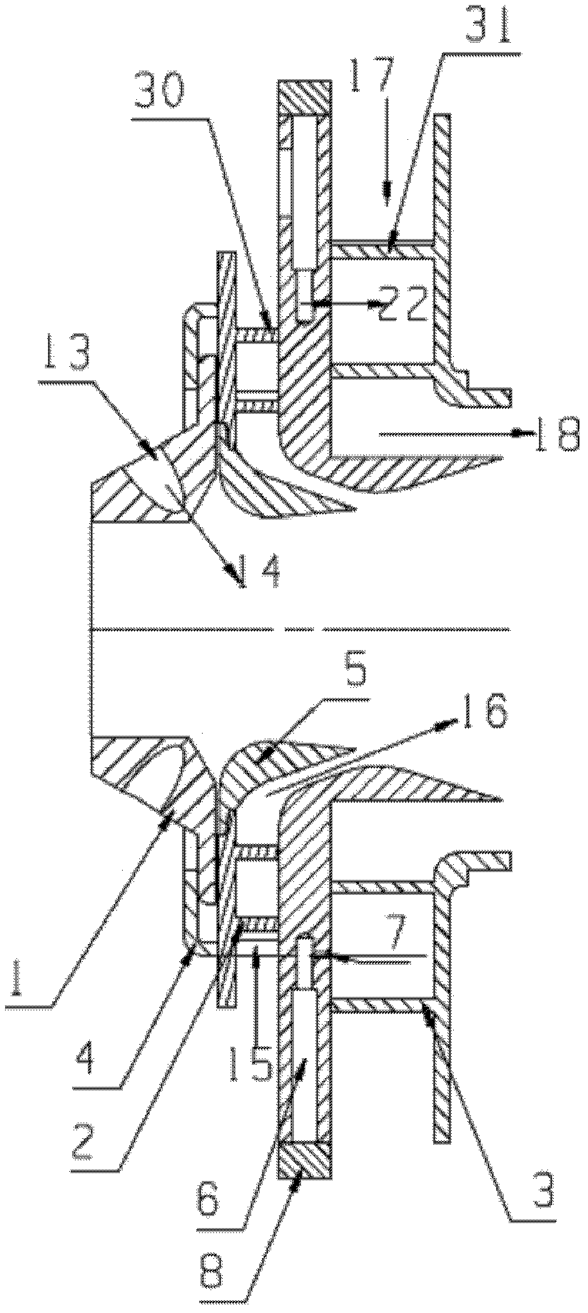
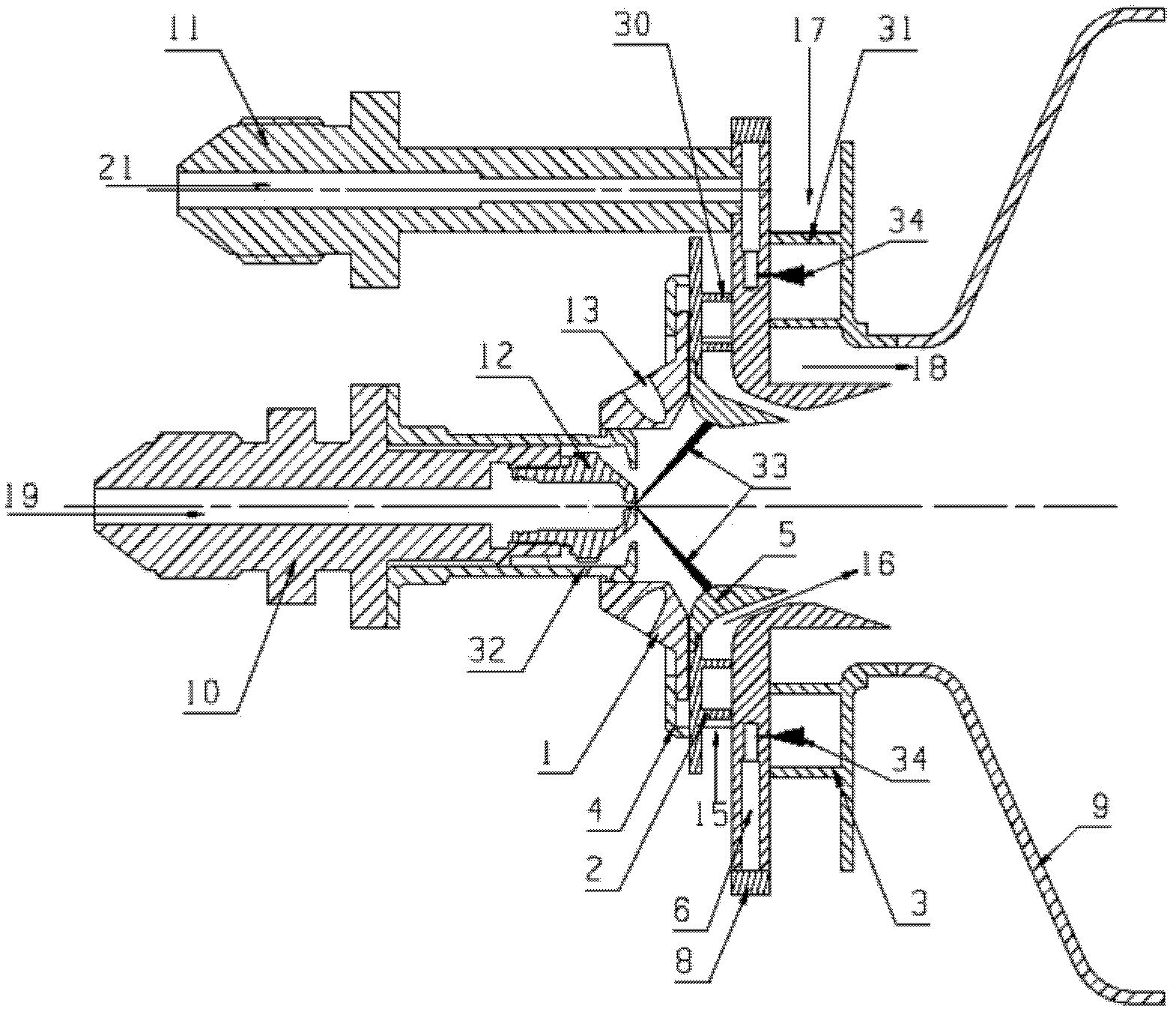
[0053] In order to make the technical solutions, implementation methods and advantages of the present invention more clear and detailed, the present invention will be further described in detail below in conjunction with the attached schematic diagrams and specific examples.

[0054] The principle of the invention is a low-pollution combustion chamber that adopts the three-stage swirl air intake of fuel oil classification: the fuel oil and the air participating in the combustion enter the combustion chamber in a graded manner, and this classification scheme is conducive to the full mixing of fuel oil and air. mix. The fuel enters the duty-level nozzle and the main combustion-level multi-point nozzle in two ways, and the air participating in the combustion enters the head of the flame tube from the third-level swirler respectively. The fuel coming in from the central duty nozzle and the inner two-stage swirling air form a duty stage. When the engine is in a low load state such ...


PUM


Abstract

The invention discloses a low-pollution combustion chamber adopting fuel-grading and three-stage cyclone air inlet. The low-pollution combustion chamber comprises an on-duty oil supply nozzle, a primary-combustion oil supply nozzle, three-stage cyclones and a flame tube. Fuel is respectively provided for the on-duty oil supply nozzle and the primary-combustion oil supply nozzle in two ways, and the three-stage coaxial cyclones supply air to the head of a combustion chamber. The two stages of cyclones on the inner side of the combustion chamber refer to an oblique-cutting hole cyclone and a radial cyclone, cyclone of the two-stage cyclones are in opposite directions. A centrifugal atomizing nozzle is arranged at the center of the oblique-cutting hole cyclone, and the second-stage cyclone on the inner side are combined and matched with a center on-duty nozzle. The cyclone on the outside of the combustion chamber is a radial cyclone with cyclone direction opposite to that of a second-stage cyclone. Primary combustion fuel enters a cyclone blade channel from small holes of a front wall surface of a third-stage cyclones by way of multipoint direct injection and is accelerated to be crushed and atomized in a cyclone channel to be mixed with the air, and forms premixed or partly premixed fuel-air mixture at an exit of the tertiary swirling influx to enter a primary combustion zone to be combusted. The low-pollution combustion chamber is applicable to aircraft engine combustion chambers or industry fuel turbine combustion chambers.

Description

technical field [0001] The invention relates to the technical field of engines, and is a low-pollution combustion chamber that adopts three-stage swirl air intake of fuel graded air. The work can significantly reduce the emission of pollutants. Background technique [0002] In order to meet the requirements that the large bypass for civil aircraft in the future will be more economical, more environmentally friendly and safer than turbofan engines, the International Civil Aviation Organization (ICAO) has specified the pollutants of aviation gas turbines, especially NO X Emission requirements are becoming more and more stringent, and several major aviation industry countries and several major gas turbine companies are targeting NO, which is the most harmful to the environment. X Emissions outstanding issue, NO in aero-engine research X Extensive research has been carried out as a key topic on the control of . In achieving low NO X A series of achievements have been made in...

Claims


Application Information

Patent Timeline
Patent Type & Authority Applications(China)
IPC IPC(8): F23R3/58
Inventor 刘富强刘存喜杨金虎穆勇徐纲朱俊强
Owner 中科航空动力(株洲)装备制造研究院有限公司
Why Eureka
Try Eureka