LED (light emitted diode) line scanning optical system applied to confocal microscopy

A confocal microscope and optical system technology, applied in optics, microscopes, optical components, etc., can solve problems such as aberration, resolution reduction, aberration, distortion, etc., and achieve the effect of reducing system complexity and debugging difficulty

Inactive Publication Date: 2013-09-25
SUZHOU INST OF BIOMEDICAL ENG & TECH CHINESE ACADEMY OF SCI
View PDF6 Cites 9 Cited by
  • Summary
  • Abstract
  • Description
  • Claims
  • Application Information

AI Technical Summary

Problems solved by technology

[0006] The traditional confocal point scanning imaging mode using a laser light source has the following disadvantages: (1) The system is composed of large-volume optical components (such as multiple sets of lasers), which makes the system configuration very complicated, bulky and expensive; (2) If the laser beam There is a deviation between the convergence

Method used


Image

  • LED (light emitted diode) line scanning optical system applied to confocal microscopy
  • LED (light emitted diode) line scanning optical system applied to confocal microscopy
  • LED (light emitted diode) line scanning optical system applied to confocal microscopy

Examples


Embodiment Construction

[0027] The present invention will be described in detail below with reference to the accompanying drawings and in combination with embodiments.

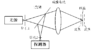
[0028] refer to figure 1 As shown, an LED line-scanning optical system applied in confocal microscopy includes a high-brightness LED light source module 1. The brightness LED module 1 is provided with an LED light-emitting chip, and the front of the LED light-emitting chip is arranged There is a uniform light coupling module 2, a focusing lens 3 is arranged in front of the uniform light coupling module 2, a first slit 4 is arranged in front of the focusing lens 3, and a dichroic mirror 5 is sequentially arranged behind the first slit, Imaging system 6 , second slit 7 and object plane 8 .

[0029] Further, the dichroic mirror 5, the imaging system 6, the second slit 7 and the object surface 8 form an illumination optical path, and the direction perpendicular to the illumination optical path is a signal receiving optical path, and the...


PUM


Abstract

The invention discloses an LED (light emitted diode) line scanning optical system applied to a confocal microscopy. The LED line scanning optical system comprises a high-luminance LED light source module which is provided with an LED luminous chip, wherein a dodging coupling module is arranged right ahead of the LED luminous chip, a focusing lens is arranged in front of the dodging coupling module, a first slit is formed in front of the focusing lens, and a dichroscope, an imaging system, a second slit and an object plane are successively arranged behind the first slit. By adopting the technical scheme disclosed by the invention, the ideal line light source excitation is realized, the LED line scanning optical system is completely equal to a plurality of laser light sources large in size and high in price in the function aspect, and more importantly, the line light source excitation which can not be realized by the laser light sources is obtained; the complexity and the debugging difficulty of the system are greatly reduced.

Description

technical field [0001] The invention belongs to the field of optical imaging, in particular to an LED line scanning optical system applied in confocal microscopy. Background technique [0002] Since its invention, confocal microscopy has been deeply researched and widely used, especially after it has been proved by experiments that it has unique depth resolution and can realize optical tomography for biological samples. The optical tomography property of confocal microscopy allows people to cut thick samples into thin slices in a non-destructive way, and then use a computer to synthesize the tomographic images into a three-dimensional image. [0003] At present, confocal microscopy mainly adopts laser confocal point scanning method, adopts laser light source as excitation light source, removes interfering light through confocal optical path, and converges laser light into points to excite fluorescence, which has high detection sensitivity, but imaging requires two dimension...

Claims


Application Information

Patent Timeline
IPC IPC(8): G01N21/64G02B21/36G02B27/09
Inventor 熊大曦杨西斌
Owner SUZHOU INST OF BIOMEDICAL ENG & TECH CHINESE ACADEMY OF SCI
Why Eureka
Try Eureka