Low-power-consumption rapid capacitor switching switch with intelligent control

A capacitor switching and intelligent control technology, applied in reactive power compensation, reactive power adjustment/elimination/compensation, etc., can solve the problems of reactive power compensation, large steepness, and impossibility

Active Publication Date: 2013-09-25
江苏南自通华智慧能源股份有限公司 +1
View PDF5 Cites 0 Cited by
  • Summary
  • Abstract
  • Description
  • Claims
  • Application Information

AI Technical Summary

Problems solved by technology

[0004] Existing industries such as metallurgy, welding machines, and vibration have fast-changing and steep operation modes, and the frequency of load changes can reach about 20ms sometimes. Effective reactive power compensation cannot be performed, which is extremely unfavorable to power grid operation and users.

Method used


Image

  • Low-power-consumption rapid capacitor switching switch with intelligent control
  • Low-power-consumption rapid capacitor switching switch with intelligent control
  • Low-power-consumption rapid capacitor switching switch with intelligent control

Examples


Embodiment 1

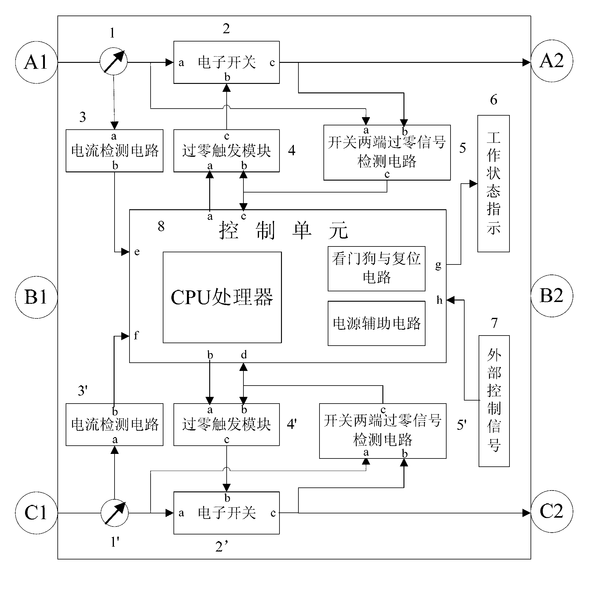
[0050] Combine below figure 1 Describe this embodiment. The low-power fast capacitor switching switch with intelligent control described in this embodiment includes three-phase power input A1, B1, C1, three-phase control output A2, B2, C2, electronic switch 2 , 2', current transformer 1, 1', zero-crossing signal detection circuit at both ends of the switch 5, 5', zero-crossing trigger module 4, 4', current detection circuit 3, 3', working status indication 6, external control signal 7. Control unit 8.

[0051] The input terminal a of the electronic switch 2 is connected to the power supply input A1 through the current transformer 1 and connected to the A-phase power input of the three-phase power supply input, and the output terminal c of the electronic switch 2 is connected to the first terminal of the three-phase power capacitor through the control output A2 , the power input B1 is directly connected to the B phase of the three-phase power input, the control output B2 is co...


PUM


Abstract

The invention discloses a capacitor switching switch. The switch comprises a three-phase source input end, a three-phase control output end, first and second electronic switches, first and second current transformers, first and second switch two-end zero-crossing signal detecting circuits, first and second zero-crossing trigger modules; first and second current detecting circuits and a control unit, wherein the first current transformer and the first electronic switch are sequentially connected in series between a first input end and a first output end; the first input end is connected with the A phase of three-phase source input; the first output end is connected with the first end of a three-phase power capacitor; the first current transformer is connected with the first current detecting circuit; the first switch two-end zero-crossing signal detecting circuit is located at two ends of the first electronic switch; the first zero-crossing trigger module is directly connected with the first electronic switch; the control unit is connected with the first current detecting circuit, the first switch two-end zero-crossing signal detecting circuit and the first zero-crossing trigger module respectively; a C circuit is same as an A circuit.

Description

technical field [0001] The invention relates to a low-power fast capacitor switching switch with intelligent control, in particular to a low-power switching switch that can be conveniently applied to various occasions requiring voltage zero-crossing and frequent and fast switching. Background technique [0002] In the current power reactive power compensation system, zero-crossing switching switches such as thyristors, synchronous switches, and composite switches are widely used to switch the voltage of power capacitors at zero-crossing. Accurate connection at the voltage zero-crossing point requires the detection accuracy and anti-interference ability of the voltage zero-crossing detection circuit at both ends of the main circuit switch. The width of the zero-crossing signal of the terminal output voltage is wide, resulting in a large gap between the switch-on time and the actual zero-crossing time. With the development of modern industry, frequency conversion and rectifica...

Claims


Application Information

Patent Timeline
Patent Type & Authority Applications(China)
IPC IPC(8): H02J3/18
CPCY02E40/30
Inventor 徐魁许有勇常新平殷杰方健
Owner 江苏南自通华智慧能源股份有限公司
Why Eureka
Try Eureka