Power generator and power generating system

A technology of power generation device and generator, which is applied in wind power generation, wind turbine assembly, engine and other directions, and can solve problems such as changing the pitch angle

Inactive Publication Date: 2013-10-30
YASKAWA DENKI KK
View PDF5 Cites 5 Cited by
  • Summary
  • Abstract
  • Description
  • Claims
  • Application Information

AI Technical Summary

Problems solved by technology

[0004] However, the technique disclosed in Japanese Patent Application Laid-Open No. 2003-113769 fails to individually change the pitch angle of each blade according to the position of each blade

Method used


Image

  • Power generator and power generating system
  • Power generator and power generating system
  • Power generator and power generating system

Examples


Embodiment Construction

[0021] Exemplary embodiments of the power generation device and the power generation system disclosed in the present application are described in detail below with reference to the accompanying drawings. It will be noted that the following embodiments are not intended to limit the present invention.

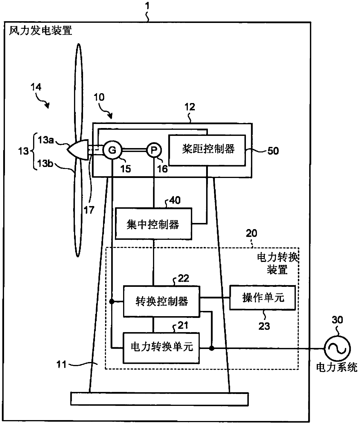
[0022] figure 1 is a schematic diagram of the configuration of the wind power generator according to the first embodiment. like figure 1 As shown in , the wind power generation device 1 according to the first embodiment includes a wind power generation unit 10 and a power conversion device 20 , and supplies power to a power system 30 . For ease of explanation, part of the construction is not in the figure 1 shown in . will refer to Figure 8 and other drawings describe configurations that are not shown.

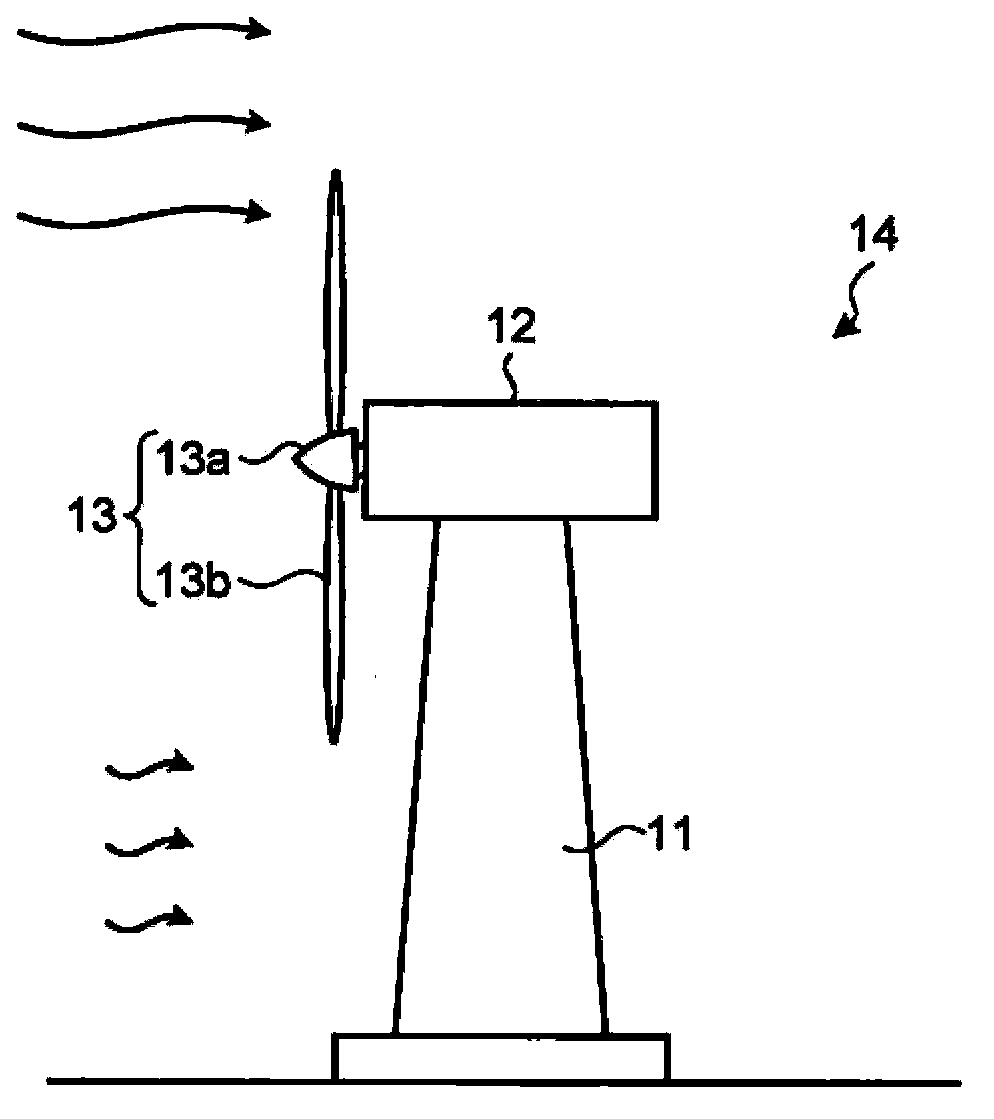
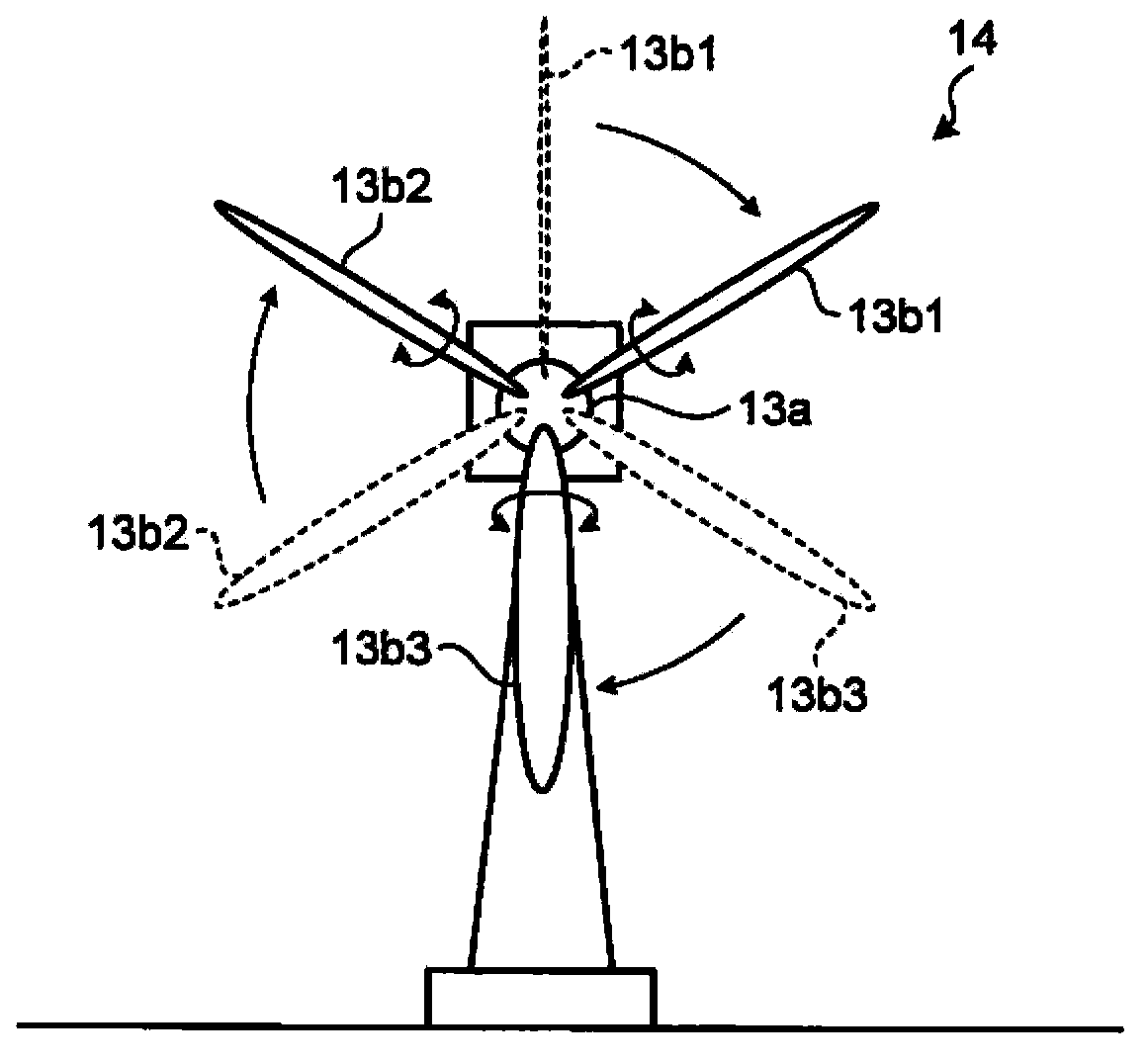
[0023] The wind power unit 10 comprises a windmill 14 with a tower 11 , a nacelle 12 and a propeller 13 . The nacelle 12 is rotatably supported by the tower body 11 . Th...


PUM


Abstract

A power generator (1, 110) according to an embodiment includes a propeller (13), a position detector (16), and a pitch controller (50). The propeller (13) includes a plurality of blades (13b1, 13b2, 13b3) whose pitch angle is changeable, and is rotated by a fluid. The position detector (16) detects the rotational position of the propeller (13). The pitch controller (50) performs pitch control processing for changing the pitch angle depending on the position of each of the blades (13b1, 13b2, 13b3) specified by the rotational position of the propeller (13).

Description

technical field [0001] The present invention relates to a power generating device and a power generating system. Background technique [0002] Conventionally, propeller type power generating devices are widely known, which generate electric power by rotating a propeller using fluid such as wind and ocean current. A wind power generator converts mechanical energy of a propeller rotating by capturing wind force into electrical energy, for example, using a generator. [0003] In recent years, in order to eliminate differences in thrust and moment between blades in a propeller-type power generation device, a method for detecting the load on each blade to individually control each blade according to the load thus detected has been developed. blade pitch angle. For example, the prior art is disclosed in Japanese Patent Application Laid-Open No. 2003-113769. [0004] However, the technique disclosed in Japanese Patent Application Laid-Open No. 2003-113769 fails to individually c...

Claims


Application Information

Patent Timeline
Patent Type & Authority Applications(China)
IPC IPC(8): F03D7/04
CPCF03D7/024Y02E10/723F05B2270/336F03D1/003Y02E10/728F05B2270/326F03D7/0224F03D1/001F05B2270/328F03D13/10F03D80/50Y02E10/72
Inventor 宫本恭祐
Owner YASKAWA DENKI KK
Why Eureka
Try Eureka