Radar test mechanism and multifunctional radar test system

A testing mechanism and testing system technology, applied to radio wave measuring systems, instruments, etc., to achieve the effect of fast and convenient adjustment

Pending Publication Date: 2021-08-03
SHANGHAI VEI SHENG AUTO PARTS MFG CO LTD
View PDF3 Cites 0 Cited by
  • Summary
  • Abstract
  • Description
  • Claims
  • Application Information

AI Technical Summary

Problems solved by technology

However, it should be pointed out that there are few professional devices on the market that can test the performance of the radar in the working environment of the radar, and there are very few devices that can test the various working environments in the working process of the radar.

Method used


Image

  • Radar test mechanism and multifunctional radar test system
  • Radar test mechanism and multifunctional radar test system
  • Radar test mechanism and multifunctional radar test system

Examples


Embodiment 1

[0050] Reference manual attached Figure 1 to Figure 7 , the radar testing mechanism provided by the present invention is described, the radar testing mechanism provided by the present invention can simulate the real temperature environment in the working process of the radar, and complete the test of the working performance of the radar in the preset temperature environment. The radar testing mechanism can also simulate the vibration environment in the working process of the radar, and complete the test of the working performance of the radar in the preset vibration frequency environment.

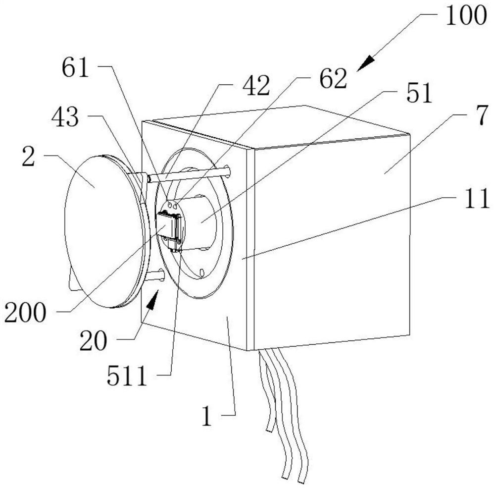
[0051] Reference manual attached Figure 3 to Figure 7 , specifically, the radar testing mechanism 100 is used to test the performance of the radar to be tested 200 in a simulated real environment, and the radar testing mechanism 100 includes a substrate 1 , a radome 2 and a temperature regulation assembly 3 . The substrate 1 has a first side 11 . The radome 2 is adapted to cover at leas...

Embodiment 2

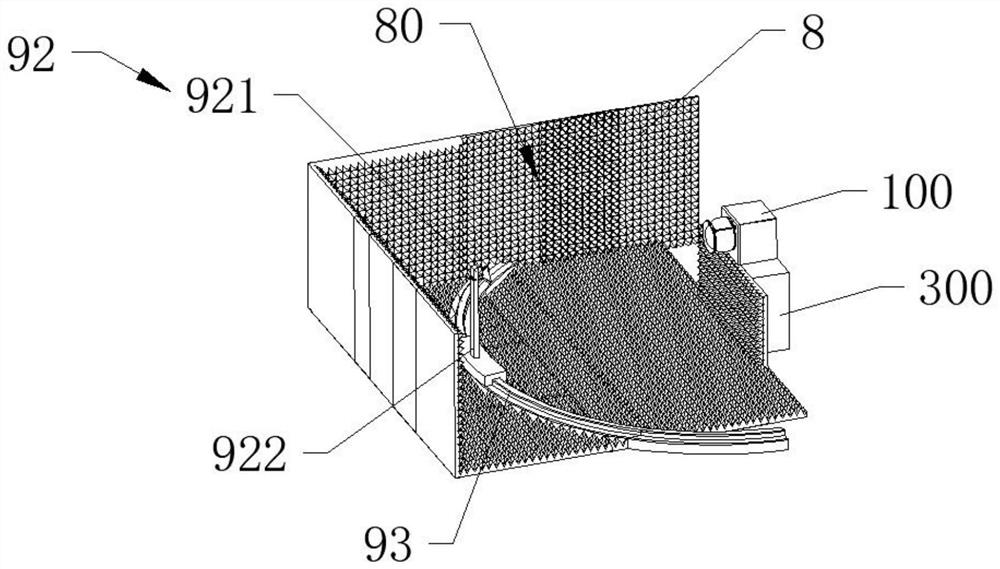
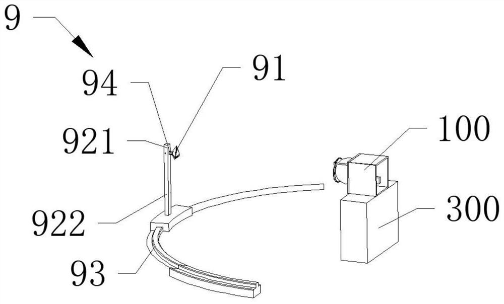
[0068] Reference manual attached Figure 1 to Figure 7 According to another aspect of the present invention, the present invention further provides a multi-functional radar testing system, including the radar testing mechanism 100 described in Embodiment 1 above, the wall body 8 and the reflector assembly 9 . The wall body 8 surrounds and forms a reflection test space 80 . The reflection assembly 9 includes a radar reflector 91, the radar reflector 91 is installed in the reflection test space 80, and the radar to be tested 200 in the temperature test space 20 of the radar test mechanism 100 faces the radar reflector 91.

[0069] Preferably, the radar reflector 91 is a corner reflector.

[0070] Reference manual attached figure 1 and figure 2 , the reflection assembly 9 further includes a pole 92 and a slide rail 93 . The pole 92 has a high end portion 921 and a low end portion 922 . The slide rail 93 is mounted on the bottom wall of the reflection test space 80, the low...


PUM


Abstract

The invention discloses a radar test mechanism and a multifunctional radar test system. The radar test mechanism comprises a substrate, a radar cover and a temperature adjusting assembly; the substrate is provided with a first side surface; the radar cover is suitable for covering at least one part of the first side surface so that a temperature testing space can be formed between the first side surface and the radar cover, and a radar to be tested is suitable for being installed in the temperature testing space; and the temperature adjusting assembly is installed on the substrate and is used for adjusting the environment temperature in the temperature testing space. The multifunctional radar test system can simulate the temperature environment in the real working process of the radar and test the working performance of the radar in a simulated temperature environment state; the multifunctional radar test system can also test the radar to be tested in a simulated vibration environment and an angle environment.

Description

technical field [0001] The invention relates to the field of radar testing, and further relates to a radar testing mechanism and a multifunctional radar testing system. Background technique [0002] Millimeter wave radar is the abbreviation of millimeter wave detection and ranging system, which is the product of the combination of millimeter wave technology and radar technology. In recent years, with the continuous development of science and technology, the degree of intelligence is getting higher and higher, and millimeter wave radar technology has made great progress and has been widely used. [0003] As a high-precision device, the millimeter-wave radar has a great impact on the performance of the radar in its working environment, such as temperature, humidity and vibration frequency. However, it should be pointed out that there are few professional devices on the market that can test the performance of radars in the working environment of radars, and there are very few ...

Claims


Application Information

Patent Timeline
Patent Type & Authority Applications(China)
IPC IPC(8): G01S7/40
CPCG01S7/40
Inventor 齐照山林东峰陈明何育林殷梓欣朱琬晴
Owner SHANGHAI VEI SHENG AUTO PARTS MFG CO LTD
Why Eureka
Try Eureka