
Suitcase handle

A luggage and handle technology, applied in the field of handle mechanism, can solve the problems of spring elastic failure, twisting deformation, automatic reset and closed state of the handle, etc.

Active Publication Date: 2013-11-20
陈宏伟
View PDF7 Cites 4 Cited by
  • Summary
  • Abstract
  • Description
  • Claims
  • Application Information

AI Technical Summary

Problems solved by technology

In the existing design, the handle and the handle seat are rotatably connected by a boss, the spring is installed on the outer surface of the boss, and the two ends of the spring are respectively fixed on the handle and the handle seat, and the handle is in the non-use state ( It is the closed state) already has a certain elastic potential energy, and the rotation of the handle increases the elastic potential energy of the spring. After use, the handle automatically returns to the closed state due to the elastic potential energy of the spring. This design is undoubtedly good, but Because the spring is installed on the outer surface of the shaft, it is easy to cause the two ends of the spring to be distorted and deformed due to too strong elastic potential energy, and finally lead to the elastic failure of the spring. In addition, when installing the spring, in order to obtain an initial elastic potential energy, it is necessary to place one end of the spring Fixed, the other end rotates at a certain angle to obtain elastic potential energy. Since there is no limit mechanism, after rotating at a certain angle, it is necessary to use a cover that covers the spring to clamp the spring, and then quickly install the cover that clamps the spring on the handle seat. The installation is obviously inconvenient, and requires high technical requirements for installation, and requires special equipment. When the spring falls during use, consumers cannot install it by themselves. If the elastic potential energy of the initial spring is too small, the handle cannot be automatically reset to the original position. closed state

Method used


Image

  • Suitcase handle
  • Suitcase handle
  • Suitcase handle

Examples


Embodiment Construction

[0020] Embodiments of the present invention will be further described below in conjunction with the accompanying drawings.

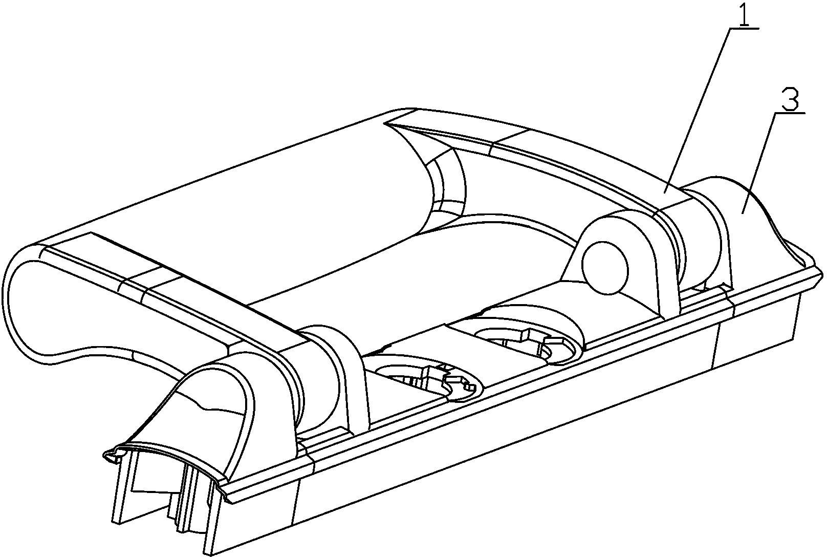
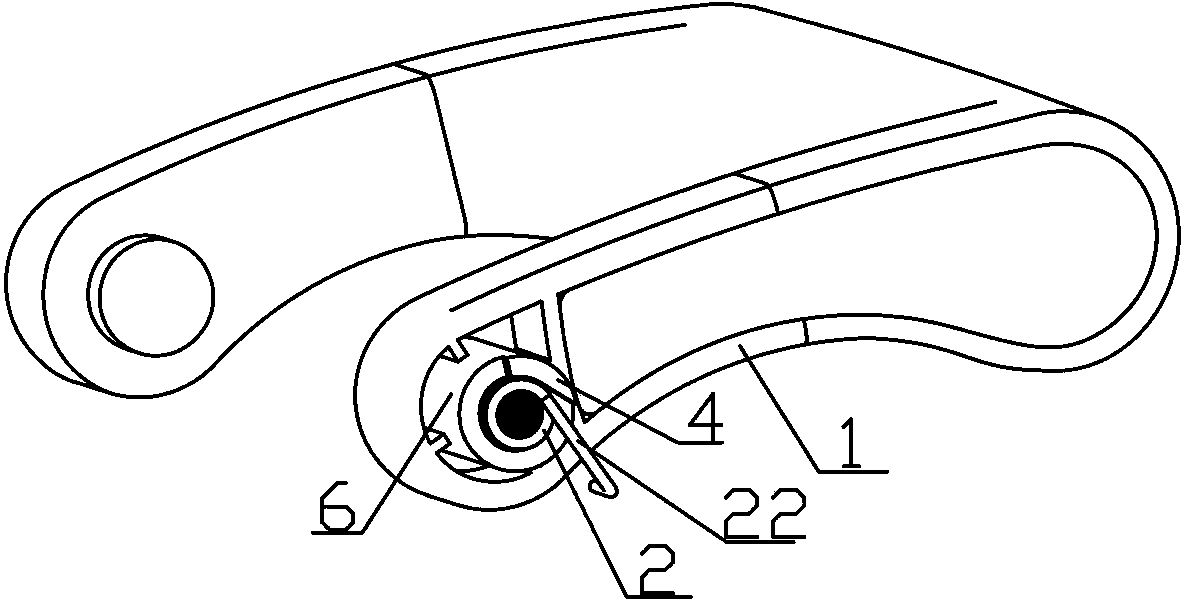
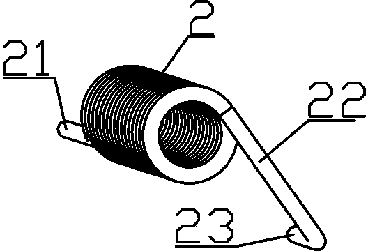
[0021] with accompanying drawings figure 1 , 2 , 3, 4, 7, and 8 descriptions, a luggage handle provided by the present invention includes a handle 1 and a handle seat 3, the two ends of the handle 1 are provided with bosses 6, and the handle seat 3 is provided with a boss post mounting hole 8, the protruding post 6 is rotatably installed in the protruding post mounting hole 8, the protruding post 6 is provided with a spring mounting hole 7, and a spring 2 is installed in the spring mounting hole 7, and the spring 2 is inserted into One end in the spring mounting hole 7 is provided with a fixed rod 21, and the fixed rod 21 of the spring 2 is a horizontal fixed rod 21 extending outward along the axial direction of the spring 2. The positioning hole 11 matched with the fixed rod 21 of the spring 2, the fixed rod 21 is matched with the positioning hole 11,...


PUM


Abstract

The invention provides a suitcase handle. The suitcase handle comprises a handle and a handle seat, the two ends of the handle are both provided with a protruding column, the handle seat is provided with protruding column installation holes, the protruding columns are rotatingly arranged in the protruding column installation holes, both protruding columns are provided with a spring installation hole, both spring installation holes are provided with a spring, the ends, which are inserted into the spring installation holes, of the springs are provided with fixing rods, fixing mechanisms are arranged in the protruding columns of the handle, the fixing rods cooperate with the fixing mechanisms, the fixing rods of the springs are fixed in the spring installation holes of the protruding columns, the other ends of the springs are both provided with a moving rod, the moving rods abut the inner walls of the protruding column installation holes, the outer sides of the protruding columns are both provided with a limit block, the limit blocks correspond to the positions of the moving rods of the springs, and the limit blocks and the end face cooperated with the moving rods limit the moving rods to rotate in the direction of the end face. The springs of the suitcase handle are not easy to transform and fail, the installation is convenient, and the connection is firm.

Description

technical field [0001] The invention relates to a handle mechanism, in particular to a handle applied to bags. Background technique [0002] Most of the existing luggage handle designs can realize that the non-use state of the handle is closed. When in use, the handle can be rotated at a certain angle, which is convenient for people to use. After use, the handle automatically returns to the closed state, so that the handle does not It will affect the convenience of people's use of luggage because it occupies a certain space. The design of the handle of this functional bag is realized by the elastic potential energy of the spring. In the existing design, the handle and the handle seat are rotatably connected by a boss, the spring is installed on the outer surface of the boss, and the two ends of the spring are respectively fixed on the handle and the handle seat, and the handle is in the non-use state ( It is the closed state) already has a certain elastic potential energy,...

Claims


Application Information

Patent Timeline
IPC IPC(8): A45C13/26
Inventor 陈宏伟
Owner 陈宏伟
Learn More