Method and system for frequency calibration of radio frequency signal

A radio frequency signal, frequency calibration technology, applied in the direction of transmitter monitoring, etc., can solve the problems of complexity, time consumption, large deviation of the transmission frequency of electronic radio frequency equipment, etc., to achieve the effect of fast frequency calibration and avoid material loss

Active Publication Date: 2015-08-12
SPREADTRUM COMM (SHANGHAI) CO LTD
View PDF1 Cites 0 Cited by
  • Summary
  • Abstract
  • Description
  • Claims
  • Application Information

AI Technical Summary

Problems solved by technology
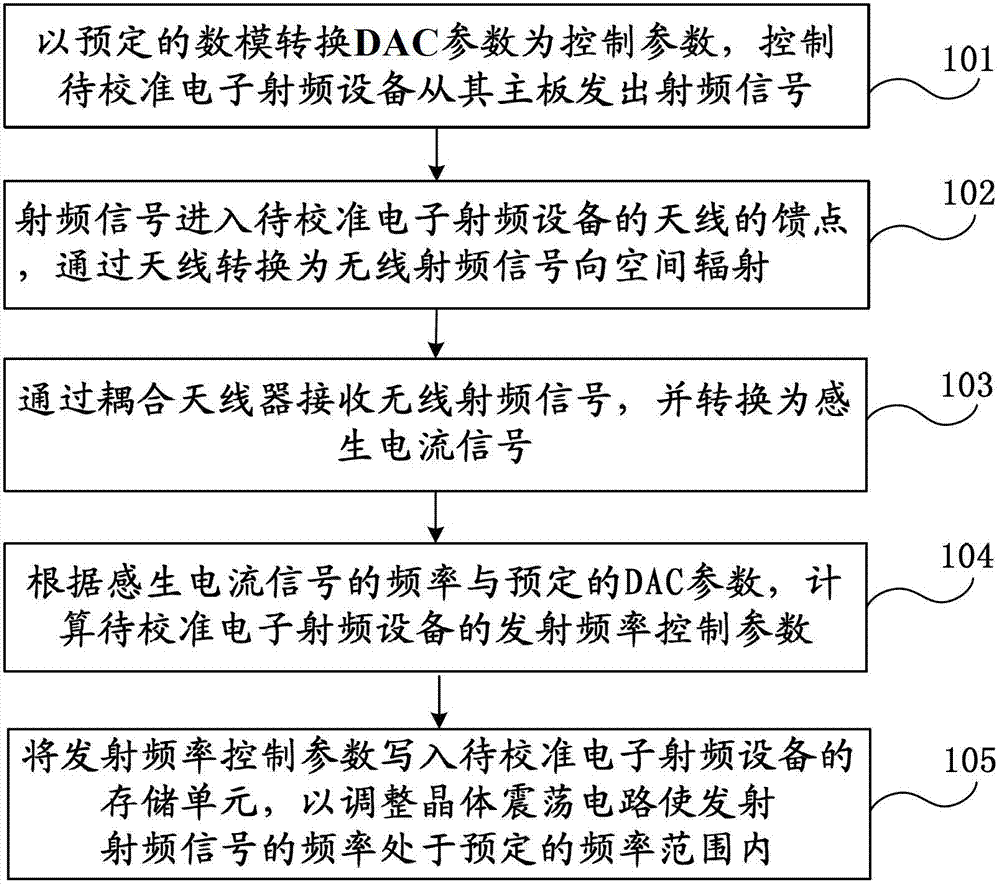
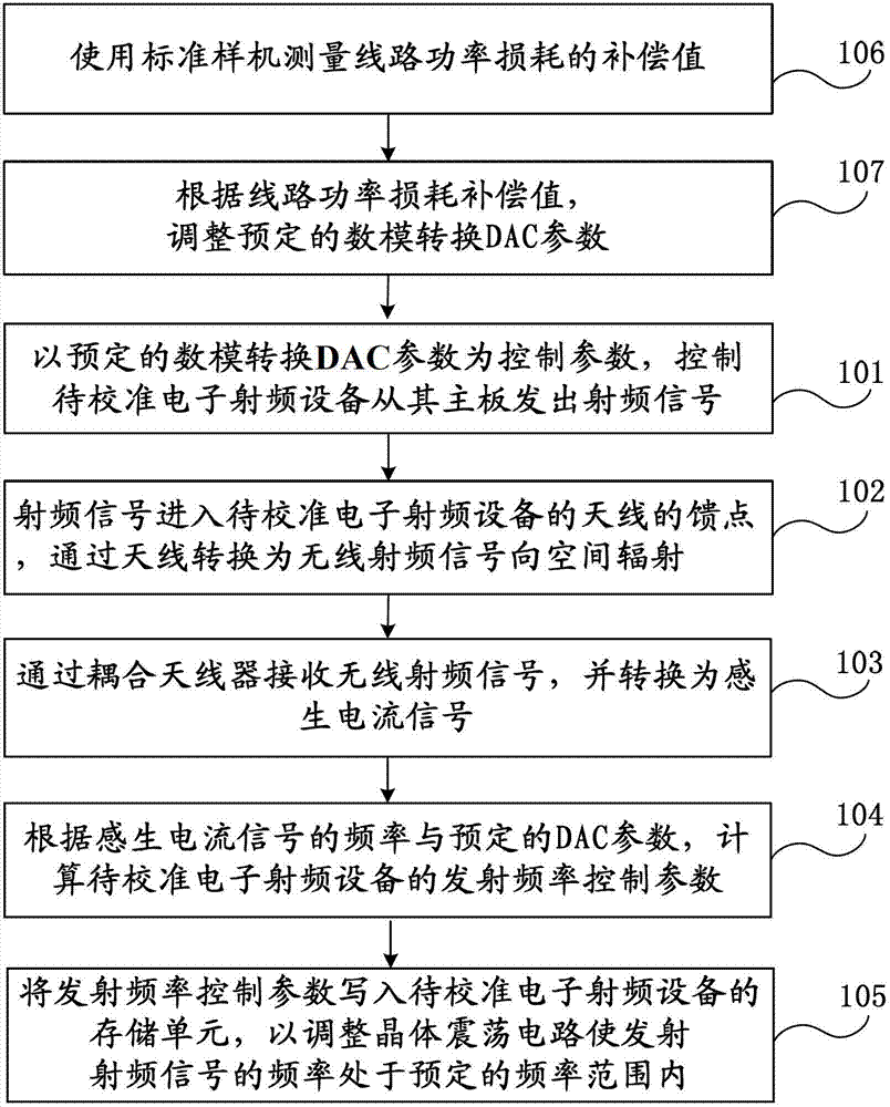
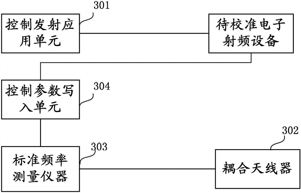
However, this method requires dismantling and re-installation of the electronic radio frequency equipment to be calibrated
In addition, in the process of disassembly and assembly, it may also cause scrapping of materials, and even affect the quality of products.
At the same time, it also leads to a lot of time consumption
In particular, if an error occurs due to a sudden problem of the radio frequency comprehensive testing instrument in the production line during the circuit board processing stage, it will cause a large deviation in the emission frequency of all electronic radio frequency equipment calibrated by the instrument within a certain period of time , it is extremely complicated and time-consuming to carry out the above-mentioned disassembly, measurement and calibration, and reinstallation of each electronic radio frequency device separately.

Method used


Image

  • Method and system for frequency calibration of radio frequency signal
  • Method and system for frequency calibration of radio frequency signal
  • Method and system for frequency calibration of radio frequency signal

Examples


Embodiment Construction

[0025] Various exemplary embodiments of the present invention will now be described in detail with reference to the accompanying drawings. It should be noted that the relative arrangement of components and steps set forth in these embodiments does not limit the scope of the invention unless specifically stated otherwise.

[0026] At the same time, it should be understood that, for the convenience of description, the sizes of the various parts shown in the drawings are not drawn according to the actual proportional relationship.

[0027] The following description of at least one exemplary embodiment is merely illustrative in nature and in no way taken as limiting the invention, its application or uses.

[0028] Techniques, methods and devices known to those of ordinary skill in the relevant art may not be discussed in detail, but where appropriate, such techniques, methods and devices should be considered part of the Authorized Specification.

[0029] In all examples shown and...


PUM


Abstract

The invention discloses a method system for frequency calibration of a radio frequency signal. The method comprises the following steps that: a to-be-calibrated electronic radio frequency device is controlled to emit a radio frequency signal from a main board by using a preset digital-to-analog conversion (DAC) parameter; the radio frequency signal enters a feed point of an antenna and is converted into a wireless radio frequency signal for radiation to space; a coupling antenna device receives the wireless radio frequency signal and the signal is converted into an induced current signal; according to the frequency of the induced current signal and the preset DAC parameter, an emission frequency control parameter is calculated; the emission frequency control parameter is written into a storage unit of the to-be-calibrated electronic radio frequency device so as to adjust a crystal oscillation circuit, so that the frequency of the radio frequency signal is within a preset frequency range. According to the invention, because the wireless radio frequency signal is used for realizing radiation from the antenna to the space and radio frequency signal transmission is realized by using the antenna coupling mode, radio frequency signal emission calibration can be realized rapidly in the integrated machine state, so that the radio frequency transmission wire utilization can be avoided and thus steps of machine dismounting and installation due to the radio frequency transmission wire utilization can be saved.

Description

technical field [0001] The invention relates to the field of electronic equipment testing, in particular to a frequency calibration method and system for radio frequency signals. Background technique [0002] For the radio frequency signal emitted by electronic radio frequency equipment, the crystal oscillation frequency inside the electronic radio frequency equipment determines the frequency of the radio frequency signal. The frequency control of the radio frequency signal can be realized by adjusting the internal crystal shock circuit of the electronic radio frequency equipment. When there is an excessive difference between the frequency of the transmitted radio frequency signal and the required frequency, the electronic radio frequency equipment will not work normally. Taking the mobile terminal as an example, when the frequency difference between the radio frequency signal transmitted by the mobile terminal and the network frequency is too large, the radio frequency sig...

Claims


Application Information

Patent Timeline
Patent Type & Authority Patents(China)
IPC IPC(8): H04B17/11H04B17/12
Inventor 游涛
Owner SPREADTRUM COMM (SHANGHAI) CO LTD
Why Eureka
Try Eureka