Method and apparatus for a crystal oscillator to achieve fast start-up time, low power and frequency calibration

a crystal oscillator and low power technology, applied in the field of crystal oscillators, can solve the problems of less accuracy, less start-up time, and low cost of crystal oscillators, and achieve the effect of accurate frequency calibration and fast start-up tim

Inactive Publication Date: 2008-03-25
MEDIATEK INC
View PDF15 Cites 48 Cited by
  • Summary
  • Abstract
  • Description
  • Claims
  • Application Information

AI Technical Summary

Benefits of technology

[0007]Briefly, one embodiment of the present invention includes a frequency generation circuit including a control module, an oscillator circuit coupled to the control module. The oscillator circuit includes an amplifier, a first capacitor coupled to the input of the amplifier and being programmable, in capacitance, by the control module, a second capacitor coupled to the output of the amplifier, a crystal resonator coupled to the input and output of the amplifier for generating an output signal having a desired frequency, wherein an inexpensive resonator, crystal or otherwise, is used as part of the crystal oscillator to achieve fast start-up time and accurate frequency calibration while using an inexpensive crystal resonator.

Problems solved by technology

Crystal oscillators are generally expensive and even more so when they are of higher frequencies.
That is, for example, the larger the ppm, the less accuracy, hence, the lower the cost of the oscillator.
In addition, crystal oscillators generally yield slow ‘start-up times’, which is defined by the duration of time required for the oscillator circuit to generate a stable and desired frequency from the time of power on.
Slow start-up times do not allow for rather frequent shut-off of the crystal oscillator when used in systems that enter, rather frequently, sleep or ‘deep sleep’ modes to reduce power consumption.

Method used


Image

  • Method and apparatus for a crystal oscillator to achieve fast start-up time, low power and frequency calibration
  • Method and apparatus for a crystal oscillator to achieve fast start-up time, low power and frequency calibration
  • Method and apparatus for a crystal oscillator to achieve fast start-up time, low power and frequency calibration

Examples


Embodiment Construction

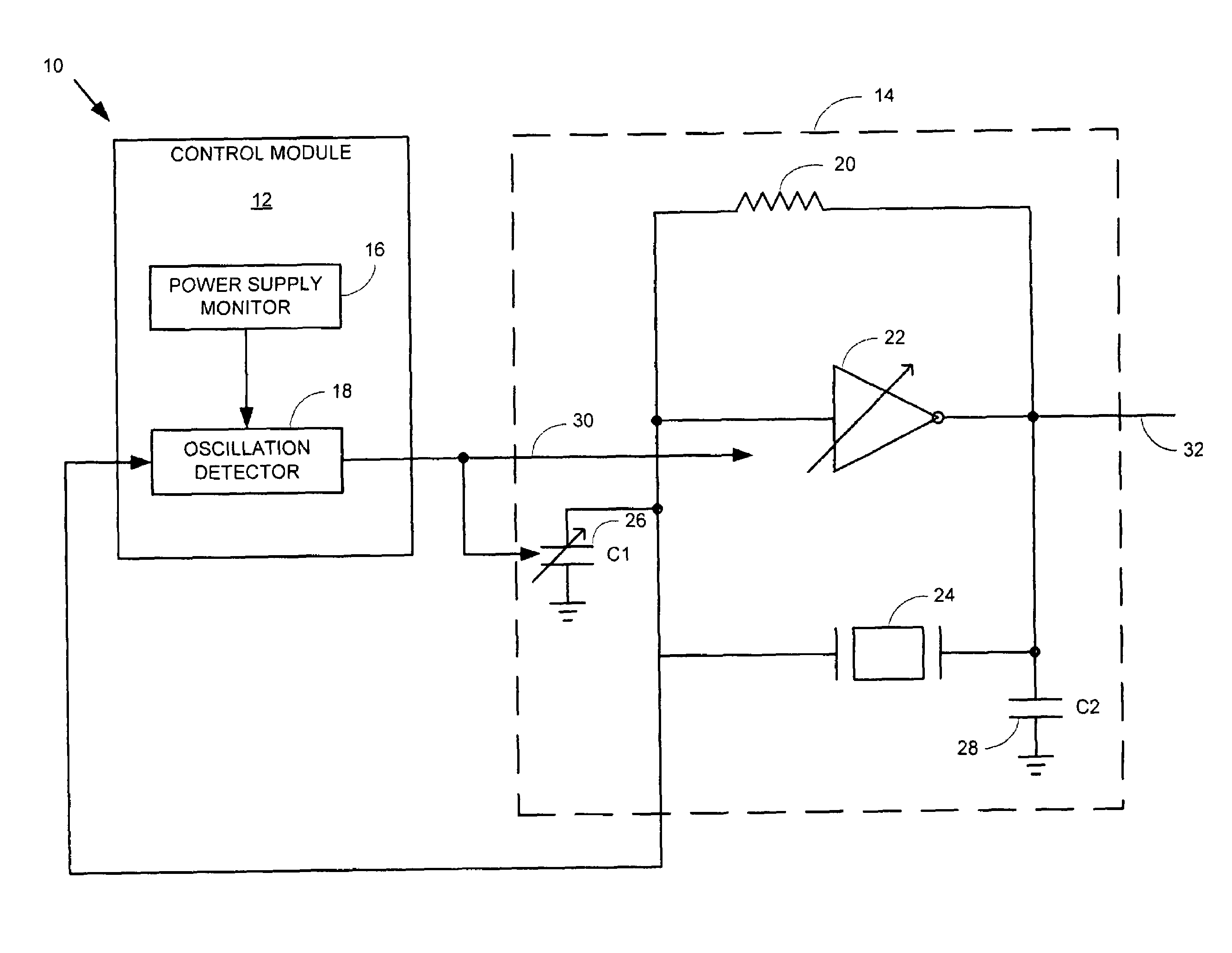
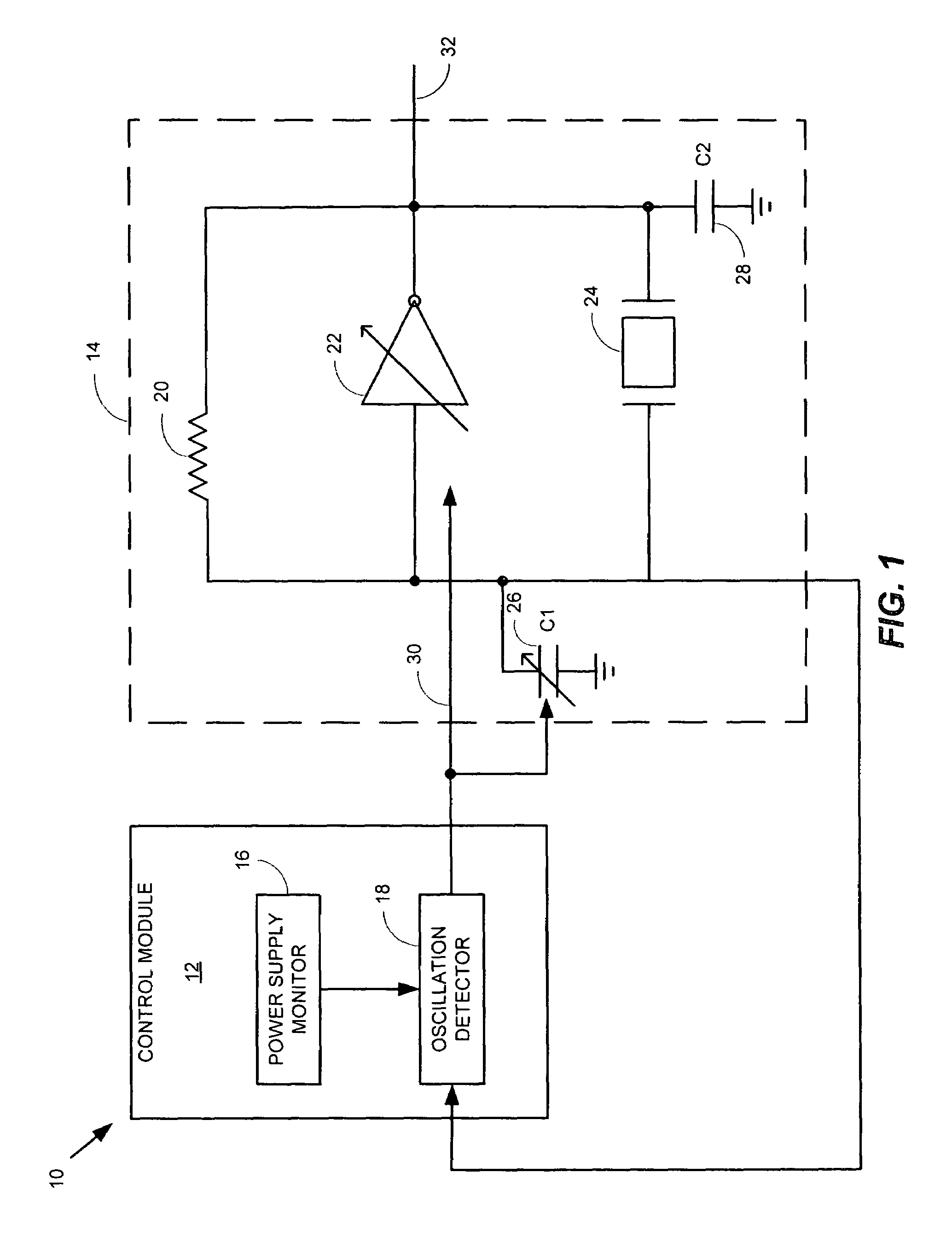
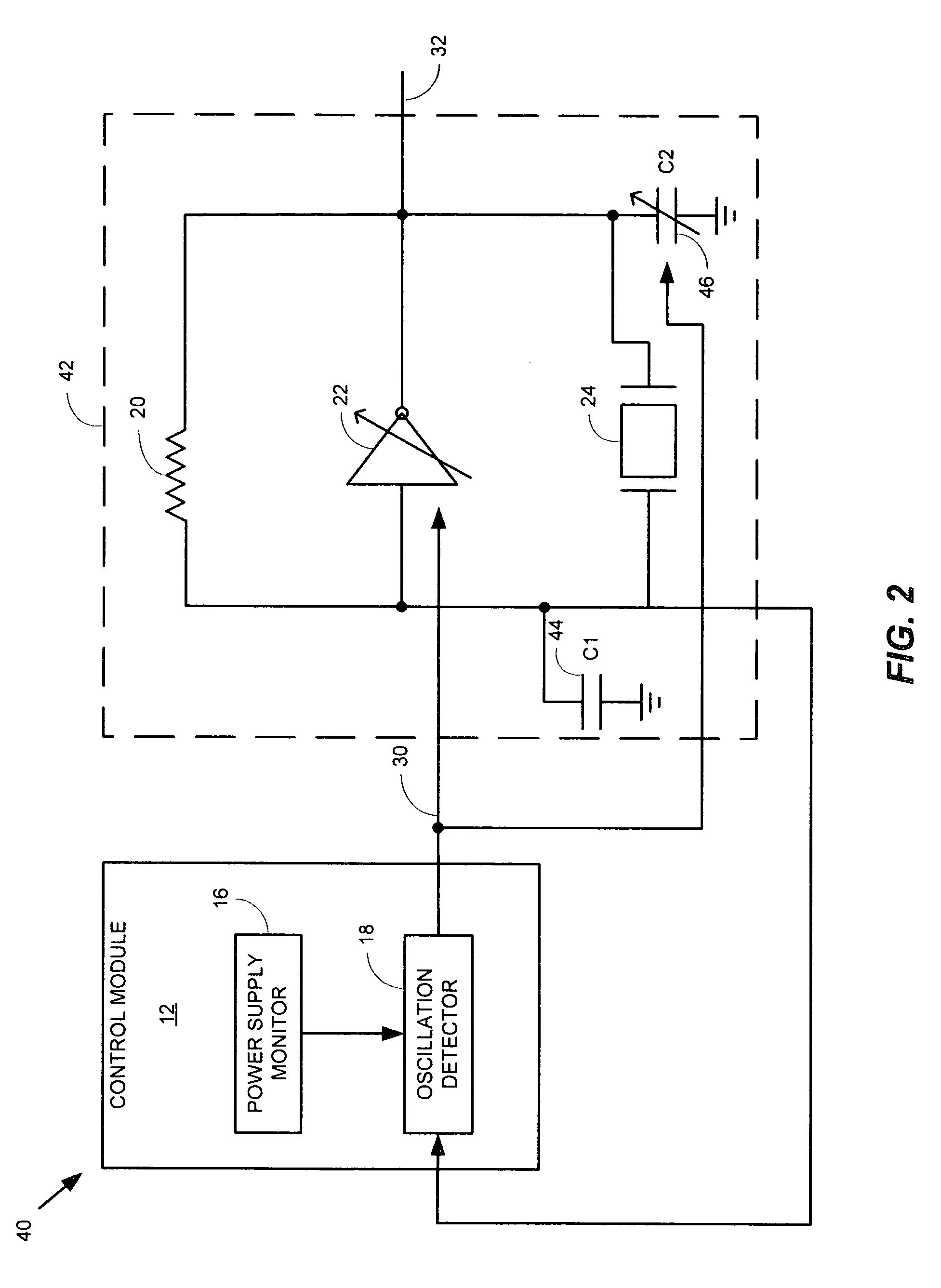
[0012]Referring now to FIG. 1, a frequency generation circuit 10 is shown to include a control module 12 coupled to an oscillator circuit 14 in accordance with an embodiment of the present invention. The control module 12 is shown to include a power supply monitor 16 coupled to an oscillation detector 18. The oscillation circuit 14 is shown to include a feedback resistor 20, an amplifier 22, a C1 capacitor 26, a crystal resonator 24 and a C2 capacitor 28. The driving current of the amplifier 22 is programmable for reasons that will become apparent shortly. The feedback resistor 20 is shown coupled, on one end, to the output of the amplifier 22 and an opposite end to the input of the amplifier 22. The input of the amplifier 22 is further shown coupled to the oscillation detector 18. The C2 capacitor 28 is shown coupled at one end to the crystal resonator 24 and to the output of the amplifier 22, generating the signal 32, and at another end to ground. The C1 capacitor 26 is shown coup...


PUM


Abstract

One embodiment of the present invention includes a frequency generation circuit including a control module, an oscillator circuit coupled to the control module, the oscillator circuit having a start-up time defined by the time required to reach a desired frequency. The oscillator circuit includes an amplifier having an input and an output and being programmably-alterable by the control module, a first capacitor coupled to the input of the amplifier and being programmably-alterable, in capacitance, by the control module, a second capacitor coupled to the output of the amplifier, a crystal resonator coupled to the first and second capacitors for generating an output signal having a desired frequency, wherein fast start-up time is achieved.

Description

BACKGROUND OF THE INVENTION[0001]1. Field of the Invention[0002]This invention relates generally to the field of crystal oscillators and particularly to accelerating the crystal oscillator's start-up time, thereby reducing its power consumption while calibrating the crystal oscillating frequency.[0003]2. Description of the Prior Art[0004]Crystal oscillators are commonly employed in electronic circuitry and particularly used for generating a system clock for a synchronous system, such as a computer or communication systems. Crystal oscillators are generally expensive and even more so when they are of higher frequencies. Crystal oscillators are generally measured in parts per million (or ppm) as a measure of the accuracy of their oscillating frequency relative to a desired frequency. That is, for example, the larger the ppm, the less accuracy, hence, the lower the cost of the oscillator. Therefore, inexpensive oscillators, for use in high-performance prior art systems, often require f...

Claims


Application Information

Patent Timeline
Patent Type & Authority Patents(United States)
IPC IPC(8): H03B5/32H03L5/00
CPCH03B5/366H03L3/00
Inventor WU, I-CHANGLO, CHUNG WENFONG, KENG LEONG
Owner MEDIATEK INC
Why Eureka
Try Eureka